
Subscribe to Our Youtube Channel
Related Manuals for Cincoze DX-1000 Series


Summary of Contents for Cincoze DX-1000 Series
- Page 1 DX-1000 Series User Manual Rugged Workstation 7/6th Generation Intel® Xeon® and Core™ Processors, Extreme Performance, Compact and Modular Rugged Workstation Version: V1.33...
-
Page 2: Table Of Contents
2.3 Definition of Switches.……...……………..........……....22 2.4 Definition of Connectors …...….……...……….....………………......23 Chapter 3 System Setup 3.1 Removing the Top Cover ……...……………………………….….…………………..28 3.2 Installing CPU ………………………………………………………………….……………31 3.3 Installing SO-DIMM Memory…………………………………..…………….……………34 3.4 Installing a Mini-PCIe/mSATA Card…………….…………….……...………………..35 3.5 Installing Antennas ………………...………..….……..………...….…………………...…36 DX-1000 Series | User Manual... - Page 3 4.3.8 Serial Port Console Redirection……………………………………….……..…..76 4.3.9 Network Stack Configuration ……….…………………………………………..77 4.3.10 CSM Configuration……..….……….…………………………………………..77 4.3.11 USB Configuration………….…………………………………………………..78 4.4 Chipset Setup …...……….…………………..…..….…..…………………………………...79 4.4.1 System Agent (SA) Configuration ……………..……………………………………..79 4.4.2 PCH-IO Configuration ………………….……………………………………………..80 4.5 Security Setup …...……….………………….…..…. …………..……………………...…82 4.5.1 Administrator Password …….…...……………………………………………………82 DX-1000 Series | User Manual...
- Page 4 5.2 Digital I/O (DIO) Hardware Specification ……………………………………………………92 5.2.1 DIO Connector Definition ………………..……...…………….......93 Chapter 6 Optional Modules 6.1 Location of the Connectors and Switches.……………………………………....96 6.2 CFM-IGN Connector Definition and Settings………………………..…………….……96 6.3 CMI-COM Connector Definition & Settings…...………………………………....97 6.4 CMI-M12 LAN Module Pin Definitions…………………………………………………….98 DX-1000 Series | User Manual...
-
Page 5: Revision
2020/11/13 Copyright Notice © 2017 by Cincoze Co., Ltd. All rights are reserved. No parts of this manual may be copied, modified, or reproduced in any form or by any means for commercial use without the prior written permission of Cincoze Co., Ltd. All information and specification provided in this manual are for reference only and remain subject to change without prior notice. -
Page 6: Product Warranty Statement
Product Warranty Statement Warranty Cincoze products are warranted by Cincoze Co., Ltd. to be free from defect in materials and workmanship for 2 years from the date of purchase by the original purchaser. During the warranty period, we shall, at our option, either repair or replace any product that proves to be defective under normal operation. -
Page 7: Technical Support And Assistance
Limitation of Liability Cincoze’ liability arising out of the manufacture, sale, or supplying of the product and its use, whether based on warranty, contract, negligence, product liability, or otherwise, shall not exceed the original selling price of the product. The remedies provided herein are the customer’s sole and exclusive remedies. -
Page 8: Conventions Used In This Manual
11. If the equipment is not used for a long time, disconnect it from the power source to avoid damage by transient overvoltage. 12. Never pour any liquid into an opening. This may cause fire or electrical shock. DX-1000 Series | User Manual... -
Page 9: Package Contents
Note: Notify your sales representative if any of the above items are missing or damaged. Ordering Information Model No. Product Description 7/6th Generation Intel® Xeon® and Core™ Processors, DX-1000-R10 Extreme Performance, Compact and Modular Rugged Workstation DX-1000 Series | User Manual... -
Page 10: Optional Modules & Accessories
GS120A24-CIN 5.0mm Pitch, with Tubes, Level VI Adapter AC/DC 24V 9.2A 220W with 3pin Terminal Block Plug GS220A24-CIN 5.0mm Pitch, with Tubes, Level VI Side-DX DX Series Side Mount Kit Din01 Dinrail Mount Kit, KMRH-K175 DX-1000 Series | User Manual... -
Page 11: Chapter 1 Product Introductions
Chapter 1 Product Introductions DX-1000 Series | User Manual... -
Page 12: Overview
1.1 Overview The Cincoze DX-1000 is a rugged workstation series based on LGA 1151 socket and Intel® C236 chipset supporting 7 generation Intel® Xeon® and Intel® Core™ Processors, DX-1000 Series supports 4K resolution through Intel® Gen 9 graphics engine with two DDR4 SO-DIMM sockets up to 64GB memory which delivers outstanding computing performance for high-end applications. -
Page 13: Product Pictures
⚫ 2x CFM Interfaces for Power Ignition Sensing and PoE Functions ⚫ 4x Full-size Mini-PCIe Slots for Wireless & I/O Expansions EN50155 / EN50121-3-2 Certification for Railway Application ⚫ ⚫ E-Mark Certification for In-vehicle Application DX-1000 Series | User Manual... -
Page 14: Hardware Specification
• 4x Full-size Mini-PCIe Sockets • In-Vehicle: E-Mark (E13, No. 10R-0514546) • 1x SIM Socket • MTBF: 457,941 Hours Storage Database: Telcordia SR-332 Issue 3, Method 1, Case 3 • 2x SATA III (6Gbps) for 2.5”HDD/SSD DX-1000 Series | User Manual... -
Page 15: System I/O
Removable 2.5” SATA HDD/SSD Bay Indicates the temperature of the system Used to insert a 2.5” SATA HDD/SSD Universal I/O Bracket SIM Card Slot Used to customized I/O output with optional Used to insert a SIM card modules DX-1000 Series | User Manual... -
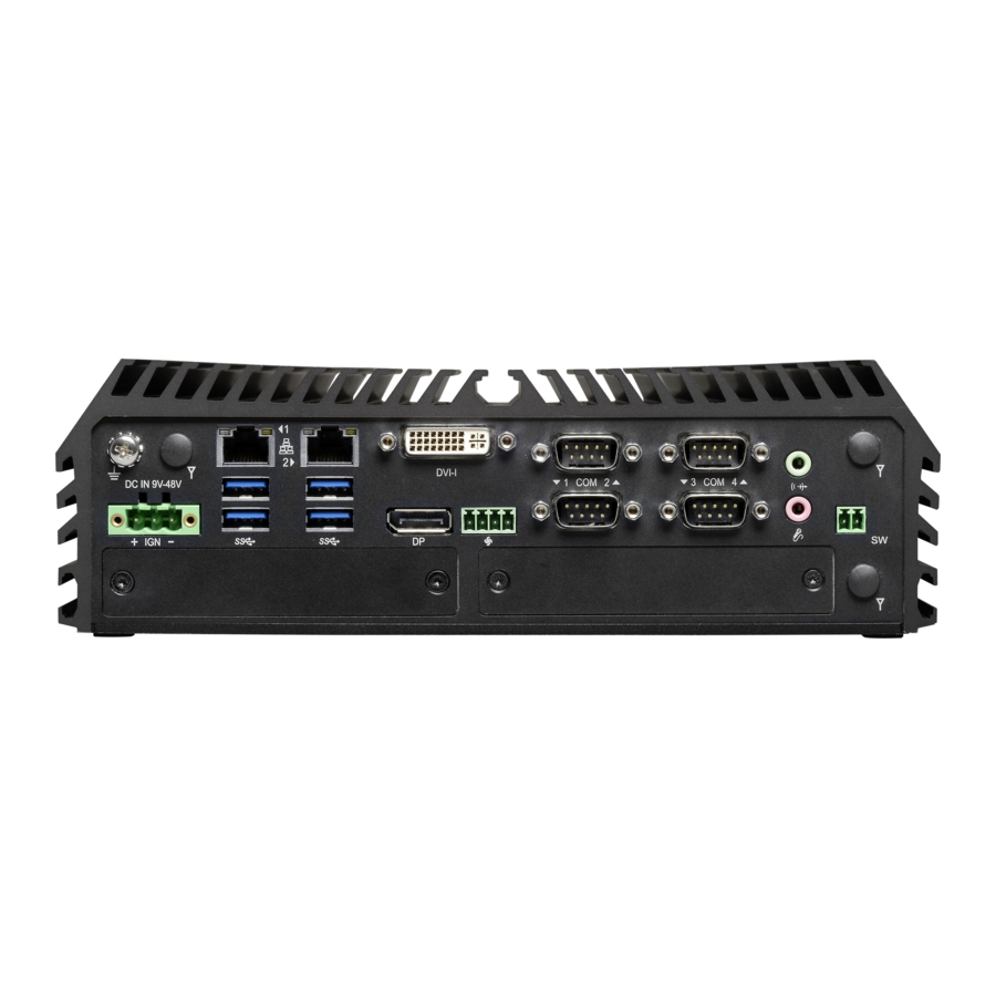
Page 16: Rear
DVI-I Port Used to connect to USB 3.0/2.0/1.1 compatible Used to connect a DVI monitor or connect devices optional split cable for dual display mode COM Port Used to connect to RS-232/422/485 serial devices DX-1000 Series | User Manual... -
Page 17: Mechanical Dimension
1.7 Mechanical Dimension DX-1000 Series | User Manual... - Page 18 Chapter 2 Switches & Connectors DX-1000 Series | User Manual...
-
Page 19: Location Of Switches And Connectors
2.1 Location of Switches and Connectors 2.1.1 Top View DX-1000 Series | User Manual... -
Page 20: Bottom View
2.1.2 Bottom View DX-1000 Series | User Manual... -
Page 21: Switches And Connectors Definition
COM1~4 with Power Select IGN Board Function Setting Super CAP SW Power 1~4 +5V / +12V Power Output 24V_12V_1 IGN Board Function Select AT_ATX1 AT / ATX Power Mode Switch CLR_CMOS1 Clear BIOS Switch Reset1 Reset Button DX-1000 Series | User Manual... -
Page 22: Definition Of Switches
0V(RI) ON (Default) ON (Default) COM4 SW3: Super CAP Switch Function Super CAP Enable (Default) Disable AT_ATX1: AT / ATX Power Mode Switch Definition 1-2 (Left) AT Power Mode 2-3 (Right) ATX Power Mode (Default) DX-1000 Series | User Manual... -
Page 23: Definition Of Connectors
Data Activity Steady Green 1Gbps Network Link No Activity Steady Orange 100Mbps Network Link 10Mbps Network Link DC_IN1: DC Power Input Connector (+9~48V) Connector Type: Terminal Block 1x3 3-pin, 5.0mm pitch Definition +9~48VIN Ignition (IGN) DX-1000 Series | User Manual... - Page 24 (Note: Please do not apply power to the pins. This port is used to connect a switch.) COM1 / COM2 / COM3 / COM4: RS232 / RS422 / RS485 Connector Connector Type: 9-pin D-Sub RS422 / 485 RS485 RS232 Full Duplex Half Duplex Definition Definition Definition DATA - DATA + DX-1000 Series | User Manual...
- Page 25 47 CLINK_DATA 12 SIM_CLK SMB_CLK 48 +1.5V 13 REFCLK+ PETN0 / SATATN0 49 CLINK_RST 14 SIM_Reset SMB_DATA 50 GND 15 GND PETP0 / SATATP0 51 NA 16 SIM_VPP 52 +3.3V 17 NA 18 GND USB_D- DX-1000 Series | User Manual...
- Page 26 47 NA 12 NA SMB_CLK 48 +1.5V 13 REFCLK+ PETN0 / ATATN0 49 NA 14 NA SMB_DATA 50 GND 15 GND PETP0 / SATATP0 51 NA 16 NA 52 +3.3V 17 NA 18 GND USB_D- DX-1000 Series | User Manual...
-
Page 27: Chapter 3 System Setup
Chapter 3 System Setup DX-1000 Series | User Manual... -
Page 28: Removing The Top Cover
1. Turn over the unit to have the bottom side face up, loosen the 6 screws on the bottom cover and place them aside for later use. 2. Remove the bottom cover from the chassis. DX-1000 Series | User Manual... - Page 29 3. Loosen the 4 screws. Pull out 4 latches as marked on photo. 4. Hold front and rear panel and lift up the body of unit vertically. DX-1000 Series | User Manual...
- Page 30 5. Turn over the body of the unit and place it gently. DX-1000 Series | User Manual...
-
Page 31: Installing Cpu
3.2 Installing the CPU Locate the CPU socket, remove the protection cover on it. Press the CPU socket lever and pull it aside away from the socket to unlock it. Pull back the lever to open the socket. DX-1000 Series | User Manual... - Page 32 Align the notches on CPU with the alignment post on socket. The notches of socket provide the space for fingers while lowering the CPU, hold the CPU by the edges toward the notches and insert the CPU gently. DX-1000 Series | User Manual...
- Page 33 Flip the corner of thermal pad and fasten the heat sink with provided 4 screws. Note: Before assembling the system’s chassis cover, please make sure the protective film on the Thermal Pad has been removed! DX-1000 Series | User Manual...
-
Page 34: Installing So-Dimm Memory
2. Insert a SO-DIMM at a 45-degree angle until its edge connector is connected to SO-DIMM socket firmly. 45° 45° Lower socket Upper socket 3. Press down the module until the retaining clips snap back in place. Lower socket Upper socket DX-1000 Series | User Manual... -
Page 35: Installing A Mini-Pcie/Msata Card
Insert the Mini-PCIe card at a 45-degree angle until its edge connector is connected firmly into slot. For 3G/4G Mini-PCIe card, please install on CN3 slot. 45° 45° CN3,4,5,6 slot CN3 slot Press the card down and secure it with 2 screws. DX-1000 Series | User Manual... -
Page 36: Installing Antennas
3.5 Installing Antennas 1. Remove the antenna rubber covers on rear panel. 2. Penetrate the antenna jack through the hole at both sides as illustrated. DX-1000 Series | User Manual... - Page 37 3. Put on washer and fasten the nut with antenna jack. 4. Assemble the antenna and antenna jack together. 5. Attach the RF connector at another end of cable onto the module. DX-1000 Series | User Manual...
-
Page 38: Installing A Cfm-Ign Power Ignition Module
3.6 Installing a CFM-IGN Power Ignition Module 1. Locate the IGN connector on the bottom side of system. 2. Fasten 1 copper pillar before insert IGN module. DX-1000 Series | User Manual... - Page 39 3. Insert IGN module vertically to the female connector on the system’s mainboard, and fasten 2 screws to fix it. DX-1000 Series | User Manual...
-
Page 40: Installing A Cmi-Com Module
3.7 Installing a CMI-COM Module 1. Locate the connector of CMI-module on the bottom side of system. 2. Loosen the 2 screws on rear bezel to remove the cover plate. DX-1000 Series | User Manual... - Page 41 3. Insert the CMI-COM module carefully into the CMI connector on main board. Fix it with 2 screws. 4. Loosen the 4 D-Sub jack screws as marked on photo. Attach the COM bracket. Fasten 2 screws and 4 D-Sub jack screws to fix it.. DX-1000 Series | User Manual...
-
Page 42: Installing A Cmi-Dio Module
3.8 Installing a CMI-DIO Module 1. Locate the connector of CMI-DIO module on the bottom side of system. 2. Loosen the 2 screws on rear bezel to remove the cover plate. DX-1000 Series | User Manual... - Page 43 3. Insert the CMI-DIO module carefully into the CMI connector on main board. Fix it with 2 screws. 4. Attach the DIO bracket, and fasten 2 screws to fix it. DX-1000 Series | User Manual...
-
Page 44: Installing Cmi-M12Lan Module
3.9 Installing CMI-M12LAN Module Note: The photo example in this section is illustrated by CMI-M12LAN01-R12/UB0910 module as shown in below picture. 1. Loosen the 2 screws on front bezel to remove the cover plate. DX-1000 Series | User Manual... - Page 45 2. Remove 4 rubber rings on M12 jacks; Penetrate M12 jacks of CMI module through the accompanying M12 I/O bracket. then fasten 4 ring hexes onto jacks as illustrated in right hand picture below. Rubber rings 3. Locate the CMI connector on the top side of system. DX-1000 Series | User Manual...
- Page 46 4. Exchange screw to copper pillar before insert the CMI module. 5. Insert the CMI module vertically into the female connector on system’s mainboard until it’s connected firmly and fasten 4 screws to fix it. 6. Fasten 2 screws on cover plate. DX-1000 Series | User Manual...
-
Page 47: Installing A Cfm-Poe Module
(Note: Please don’t block the LED.) 2. Insert the CMI-M12 module vertically into the female connector on system’s mainboard until it’s connected firmly, and fasten 4 copper pillars to fix it. DX-1000 Series | User Manual... - Page 48 Note: Before putting on the thermal block (in the next step), please make sure the protective film on the Thermal Pad has been removed! 5. Please paste the heatsink onto the CMI-PoE module carefully and connect the PoE module to the CMI-M12 module. DX-1000 Series | User Manual...
- Page 49 6. Fasten 4 screws to fix it. 7. Please paste the thermal pad onto the heatsink carefully. Note: Before assembling the system’s chassis cover, please make sure the protective film on the Thermal Pad has been removed! DX-1000 Series | User Manual...
-
Page 50: Installing Thermal Pad
3.11 Installing Thermal Pad Note: The DX-1000 series don’t need to additional installation of the PCH thermal pad. Thermal pad Note: Before assembling the system’s chassis cover, please make sure the protective film on the Thermal Pad has been removed! 3.12 Installing Top Cover... -
Page 51: Installing Bottom Cover
3.13 Installing Bottom Cover 1. Place the bottom cover back to system. 2. Fasten the bottom cover with 6 screws. DX-1000 Series | User Manual... -
Page 52: Removing The Front Cover Plate
Note: It’s advised to fasten the 2 screws manually. If fastened with an electrical screw driver, please set the torque of the driver to 2.5KgF. 3.15 Installing a SATA Hard Drive at Front Side 1. Locate the removable HDD bay and loosen the screw. DX-1000 Series | User Manual... - Page 53 3. Make the bottom side of the HDD face up, place the HDD bracket on it. Ensure the direction of bracket is correct and use 4 provided screws to assemble HDD and HDD bracket together. DX-1000 Series | User Manual...
- Page 54 4. Align the HDD bracket assembly with the entrance of removable HDD bay. Holding the rotating arm and insert the HDD bracket until the connector of HDD contact the SATA connector firmly. 5. Place the rotating arm back and fasten the screw. DX-1000 Series | User Manual...
-
Page 55: Installing A Sim Card
3.16 Installing a SIM Card 1. Locate the SIM card slot at front side. 2. Insert a SIM card into SIM slot with the gold contacts facing up. Please pay attention to the insert orientation as illustrated. DX-1000 Series | User Manual... -
Page 56: Installing The Cmos Battery
3.17 Installing the CMOS Battery 1. Locate the removable CMOS Battery and loosen the screw. 2. Pull out the CMOS battery bracket with assistance of a tweezer. DX-1000 Series | User Manual... - Page 57 3. Insert a CMOS battery in the battery slot. 4. Insert the battery bracket firmly and fasten the screw. DX-1000 Series | User Manual...
-
Page 58: Fastening The Cover
3.18 Fastening the Cover 1. Fasten the cover by using the two screws. 3.19 Installing an External Fan 1. Prepare an external fan. Loosen the 2 screws halfway on mounting frame before attempting to install it. DX-1000 Series | User Manual... - Page 59 2. Slide the FAN into the middle groove of chassis as illustrated. Tighten the 2 screws to fix it onto chassis. 3. Move the fan to the center of chassis. Tighten the 2 screws marked on photo to secure it. DX-1000 Series | User Manual...
- Page 60 4. Connect the FAN cable to external fan power connector at rear panel. DX-1000 Series | User Manual...
-
Page 61: Wall Mount Brackets
3.20 Wall Mount Brackets DX-1000 series offers wall mount brackets that customers can install system on the wall in convenient and economical ways. 1. The mounting holes are at the bottom side of system. Use provided 8 screws to fasten the bracket on each side. -
Page 62: Din-Rail Mount Brackets
3.21 DIN-Rail Mount Brackets DX-1000 series offers DIN-Rail Mount that customer can install system on the DIN Rail. 1. Please refer to section 3.20 Wall Mount Brackets to install mounting bracket at both sides of system. 2. Fasten 2 DIN rail mounting clips to mounting brackets on both sides with provided 4 screws as illustrated. -
Page 63: Vesa Mount
DIN rail. 3.22 VESA Mount DX-1000 series supports VESA mounting that customer can mount system with panel complying with VESA 75mm and 100 mm standard for various usage. DX-1000 Series | User Manual... - Page 64 1. The following picture illustrates the installation of DX-1000 series on a VESA stand. Align the 4 screw holes of VESA stand with the screw holes on bottom side of system. Fasten 4 screws to fix it. 2. Provided below is mounted with VESA stand.
-
Page 65: Side Mount Brackets
3.23 Side Mount Brackets DX-1000 series offers Side Mount that customer can install system to the right or left side of wall to create effective of space. 1. The mounting holes are at the bottom of system. Fasten the 8 screws to fix the side mount bracket with system together. - Page 66 2. Fasten the screws through the bracket mounting hole to mount system on the wall. DX-1000 Series | User Manual...
-
Page 67: Chapter 4 Bios Setup
Chapter 4 BIOS Setup DX-1000 Series | User Manual... -
Page 68: Bios Introduction
You can use arrow keys ( ↑↓ ) to highlight the field and press <Enter> to call up the sub-menu. Then you can use the control keys to enter values and move from field to field within a sub-menu. If you want to return to the main menu, just press the <Esc >. DX-1000 Series | User Manual... -
Page 69: Main Setup
Use arrow keys to move among the items and press <Enter> to accept or enter a sub-menu. 4.2.1 System Date Set the date. Please use <Tab> to switch between date elements. 4.2.2 System Time Set the time. Please use <Tab> to switch between time elements. DX-1000 Series | User Manual... -
Page 70: Advanced Setup
With virtualization, one computer system can function as multiple virtual systems. ■ Active Process Cores Allows you to choose the number of active processor cores. Configuration options: [All] [1]. DX-1000 Series | User Manual... -
Page 71: Sata And Rst Configuration
Port 1 [Enabled] Enables or disables SATA Port 2. ❑ Serial ATA Port 3 Port 1 [Enabled] Enables or disables SATA Port 3. ❑ Serial ATA Port 4 Port 1 [Enabled] Enables or disables SATA Port 4. DX-1000 Series | User Manual... -
Page 72: Pch-Fw Configuration
RAID OROM(Option ROM) / RST(Intel® Rapid Storage Technology) driver will refer to the software feature configuration to enable or disable the storage features. ❑ HDD Unlock Enables or disables HDD Unlock. ❑ LED Locate Enables or disables LED Locate 4.3.3 PCH-FW Configuration DX-1000 Series | User Manual... -
Page 73: Acpi Settings
[Suspend Disabled]: Disables entering suspend state. [S3 (suspend to RAM)]: Enables suspend to RAM state. ■ Lock Legacy Resources [Disabled] Enables or disables Lock Legacy Resources. ■ S3 Video Repost [Enabled] Enable or disable S3 Video Repost. DX-1000 Series | User Manual... -
Page 74: F81866 Super Io Configuration
Allows you to change the IO Address & IRQ settings of the specified serial port. ❑ Onboard Serial Port 1~6 Mode [RS232] Allows you to select Serial Port Mode. Configuration options: [RS232] [RS422/RS485 Full Duplex] [RS485 Half Duplex] DX-1000 Series | User Manual... -
Page 75: Hardware Monitor
This screen displays the current status of all monitored hardware devices/components such as voltages, temperatures and all fans’ speeds. ■ PWM Fan Function [Enabled] Enables or disables PWM Fan function. 4.3.7 S5 RTC Wake Settings DX-1000 Series | User Manual... -
Page 76: Serial Port Console Redirection
Allow users to enable or disable COM0, COM1, COM2, COM3, COM4, COM5 console redirection function. COM0 = Serial Port 1 COM1 = Serial Port 2 COM2 = Serial Port 3 COM3 = Serial Port 4 COM4 = Serial Port 5 COM5 = Serial Port 6 DX-1000 Series | User Manual... -
Page 77: Network Stack Configuration
[UEFI and Legacy]: Allows booting from operating systems that support legacy option ROM or UEFI option ROM. [Legacy only]: Allows booting from operating systems that only support legacy option ROM. [UEFI only]: Allows booting from operating systems that only support UEFI option ROM. DX-1000 Series | User Manual... -
Page 78: Usb Configuration
USB support will be disabled automatically if no USB devices are connected. ■ XHCI Hand-off [Enabled] Enables or disables XHCI (USB3.0) hand-off function. Use this feature as a workaround for operating systems without XHCI hand-off support. DX-1000 Series | User Manual... -
Page 79: Chipset Setup
Enables or disables Intel® Virtualization Technology for Directed I/O (VT-d) capability. ■ Above 4GB MMIO BIOS assignment [Disabled] Enables or disables Above 4GB Memory Mapped IO BIOS assignment. This is disabled automatically when Aperture Size is set to 2048MB. DX-1000 Series | User Manual... -
Page 80: Pch-Io Configuration
Allows users to select which graphics device should be primary display or select SG for switchable graphics. Configuration options: [Auto] [IGFX] [PEG] [PCIe] ❑ Internal Graphics [Auto] Allows users to enable or disable Internal Graphics. Configuration options: [Auto] [Disabled] [Enabled] 4.4.2 PCH-IO Configuration ■ PCI Express Configuration DX-1000 Series | User Manual... - Page 81 [Keep last state]: Enters to the last power state before a power failure. ■ CN3 mSATA Function Switch [Mini-PCIe] Allows you to change Mini PCIe1 (CN3) as [Mini-PCIe] or [mSATA]. ■ CN3 USB3 Function Switch [Disabled] Enables or disables CN3 USB3 Controller. DX-1000 Series | User Manual...
-
Page 82: Security Setup
This section allows users to configure BIOS security settings. 4.5.1 Administrator Password Administrator Password controls access to the BIOS Setup utility. 4.5.2 User Password User Password controls access to the system at boot and to the BIOS Setup utility. DX-1000 Series | User Manual... -
Page 83: Boot Setup
4.6.5 New Boot Option Policy Allows you to change New Boot Option Policy. Configuration options: [Default] [Place First] [Place Last]. 4.6.6 Hard Drive BBS Priority Allows you to set the order of the legacy devices in this group. DX-1000 Series | User Manual... -
Page 84: Save & Exit
4.7.8 Save as User Defaults This item allows you to save the changes done so far as user defaults. 4.7.9 Restore User Defaults This item allows you to restore the user defaults to all the setup options. DX-1000 Series | User Manual... -
Page 85: Chapter 5 Product Application (For Dio Only)
Chapter 5 Product Application (For DIO Only) DX-1000 Series | User Manual... -
Page 86: Digital I/O (Dio) Application
5.1.1.1 Pins for Digital I/O Item Standard GPIO70 (Pin103) GPIO71 (Pin104) GPIO72 (Pin105) GPIO73 (Pin106) GPIO74 (Pin107) GPIO75 (Pin108) GPIO76 (Pin109) GPIO77 (Pin110) GPIO80 (Pin111) GPIO81 (Pin112) GPIO82 (Pin113) GPIO83 (Pin114) GPIO84 (Pin115) GPIO85 (Pin116) GPIO86 (Pin117) GPIO87 (Pin118) DX-1000 Series | User Manual... - Page 87 Following is an example to enable configuration and to disable configuration by using debug. -o 4e 87 -o 4e 87 (enable configuration) -o 4e aa (disable configuration) 5.1.1.3 Relative Registers To program the F81866A configuration registers, see the following configuration procedures. DX-1000 Series | User Manual...
- Page 88 DX-1000 Series | User Manual...
- Page 89 // Set (bit 0~7) = 0 to select GP 70~77 as Input mode. <Input Value> WriteByte(AddrPort, 0x82) // Select configuration register 82h ReadByte(DataPort, Value) // Read bit 0~7 (0xFF)= GP70 ~77 as High. <Leave the Extended Function Mode> WriteByte(AddrPort, 0xAA) DX-1000 Series | User Manual...
- Page 90 // Select configuration register 60h (High Byte address) WriteByte(DataPort, (0x0A)) WriteByte(AddrPort, 0x61) // Select configuration register 61h (Low Byte address) WriteByte(DataPort, (0x00)) <Leave the Extended Function Mode> WriteByte(AddrPort, 0xAA) Cincoze default GPIO Port base address is 0xA00h DX-1000 Series | User Manual...
- Page 91 = DI6 = DO6 (Base Base address address +3) +2) (0xA02) (0xA03) = DI7 = DO7 (Base Base address address +3) +2) (0xA02) (0xA03) = DI8 = DO8 (Base Base address address +3) +2) (0xA02) (0xA03) DX-1000 Series | User Manual...
-
Page 92: Digital I/O (Dio) Hardware Specification
DO Signal have to pull up resistor to XCOM+ for external device, the resistance will affect the pull up current Signal High Level: Pull up resistor to XCOM+ Signal Low Level: = XCOM- Sink Current: 1A (Max) DX-1000 Series | User Manual... -
Page 93: Dio Connector Definition
DIO1/DIO2: Digital Input / Output Connector Connector Type: Terminal Block 2X10 10-pin, 3.5mm pitch Pin1 Pin1 DIO1 (Digital Input) DIO2 (Digital Input) Location Definition Location Definition DC INPUT DC INPUT (XCOM+) (XCOM+) DIO1 DIO2 (XCOM-) (XCOM-) DX-1000 Series | User Manual... - Page 94 Reference Input Circuit Reference Output Circuit DX-1000 Series | User Manual...
-
Page 95: Chapter 6 Optional Modules
Chapter 6 Optional Modules Pin Definitions and Settings DX-1000 Series | User Manual... -
Page 96: Location Of The Connectors And Switches
Pin 4 Definition 0 second 1 minute 5 minutes 10 minutes 30 minutes 1 hour 2 hours Reserved (0 second) 24V_12V_1: 12V / 24V Car Battery Switch Definition 24V Car Battery Input 12V Car Battery Input DX-1000 Series | User Manual... -
Page 97: Cmi-Com Connector Definition & Settings
Full Duplex Half Duplex Definition Definition Definition DATA - DATA + SW2: COM5/COM6 Power Select Location Function DIP1 DIP2 0V(RI) ON (Default) ON (Default) COM5 Location Function DIP3 DIP4 0V(RI) ON (Default) ON (Default) COM6 DX-1000 Series | User Manual... -
Page 98: Cmi-M12 Lan Module Pin Definitions
CMI-M12 LAN Module with CFM-PoE Module Pin Definitions Connector Type: M12 A coded 8pin connector POE type: Midspan (B-Type) Definition Definition 2_LAN1_0+ 2_LAN1_0- 2_LAN1_2+ 2_LAN1_1+ (Power PIN) 2_LAN1_2- 2_LAN1_1- (Power PIN) 2_LAN1_3+ 2_LAN1_3- (Power PIN) (Power PIN) DX-1000 Series | User Manual... - Page 99 © 2020 Cincoze Co., Ltd. All rights reserved. The Cincoze logo is a registered trademark of Cincoze Co., Ltd. All other logos appearing in this catalog are the intellectual property of the respective company, product, or organization associated with the logo.
Need help?
Do you have a question about the DX-1000 Series and is the answer not in the manual?
Questions and answers