
Related Manuals for Cincoze DI-1000 Series


Summary of Contents for Cincoze DI-1000 Series
- Page 1 DI-1000 Series User Manual Rugged Embedded Computer 6th Generation Intel® Core™ (Skylake-U) High Performance, Compact and Modular Rugged Embedded Computer Version: V1.63...
-
Page 2: Table Of Contents
2.2 Switches and Connectors Definition…………………..….……………………………….22 2.3 Definition of Switches.……...……………..........……....23 2.4 Definition of Connectors …...….……...……….....………………......25 Chapter 3 System Setup 3.1 Disassembling the System for Installation…………………….….…………………..30 3.2 Installing SO-DIMM Memory…………………………………..…………….……………32 3.3 Installing a Mini-PCIe/mSATA Card …………………………………………………..34 3.4 Installing Antennas…….…….…………..……….…………………………………………..36 DI-1000 Series | User Manual... - Page 3 4.4 Chipset Setup …...……….…………………..…..….…..…………………………………...67 4.4.1 System Agent (SA) Configuration ……………..……………………………………..67 4.4.2 PCH-IO Configuration ………………….……………………………………………..68 4.5 Security Setup …...……….………………….…..………………..……………………...…70 4.5.1 Administrator Password …….…...……………………………………………………70 4.5.2 User Password …….…………………………………………………..………………70 4.6 Boot Setup …...……….….……………………………...…..….…..………..…………..71 4.7 Save & Exit …...……….….………………….…..….…..………………………....72 DI-1000 Series | User Manual...
- Page 4 5.2.1 DIO Connector Definition ………………..……...……………........81 Chapter 6 Optional Modules Pin Definitions and Settings 6.1 CMI-M12 Connector Definition and Settings……………...…………………………….…..83 6.2 CFM-IGN Connector Definition and Settings……………...…………………………….…84 6.3 Installing a High Speed CMI Module…...…………..……………………………………….85 6.4 Installing a CFM-IGN Power Ignition Module..……….…….……………………………..89 DI-1000 Series | User Manual...
-
Page 5: Revision
2020/11/13 Copyright Notice © 2017 by Cincoze Co., Ltd. All rights are reserved. No parts of this manual may be copied, modified, or reproduced in any form or by any means for commercial use without the prior written permission of Cincoze Co., Ltd. All information and specification provided in this manual are for reference only and remain subject to change without prior notice. -
Page 6: Declaration Of Conformity
Product Warranty Statement Warranty Cincoze products are warranted by Cincoze Co., Ltd. to be free from defect in materials and workmanship for 2 years from the date of purchase by the original purchaser. During the warranty period, we shall, at our option, either repair or replace any product that proves to be defective under normal operation. -
Page 7: Technical Support And Assistance
Limitation of Liability Cincoze’ liability arising out of the manufacture, sale, or supplying of the product and its use, whether based on warranty, contract, negligence, product liability, or otherwise, shall not exceed the original selling price of the product. The remedies provided herein are the customer’s sole and exclusive remedies. -
Page 8: Conventions Used In This Manual
11. If the equipment is not used for a long time, disconnect it from the power source to avoid damage by transient overvoltage. 12. Never pour any liquid into an opening. This may cause fire or electrical shock. DI-1000 Series | User Manual... - Page 9 The equipment has obvious signs of breakage. ⚫ 14. CAUTION: Danger of explosion if battery is incorrectly replaced. Replace only with the same or equivalent type recommended by the manufacturer. 15. Equipment intended only for use in a RESTRICTED ACCESS AREA. DI-1000 Series | User Manual...
-
Page 10: Package Contents
Generation Intel® Core™ i3-6100U High Performance, Compact DI-1000-i3 and Modular Rugged Embedded Computer Generation Intel® Core™ i5-6300U High Performance, Compact DI-1000-i5 and Modular Rugged Embedded Computer 6th Gen. Intel® Core™ i7-6600U High Performance, Compact and DI-1000-i7 Modular Rugged Embedded Computer DI-1000 Series | User Manual... -
Page 11: Optional Modules & Accessories
SIDE Mount Kit Adapter AC/DC 12V 5A 60W with 3pin Terminal Block Plug GST60A12-CIN1 5.0mm Pitch, with Tubes, Level VI Adapter AC/DC 24V 5A 120W with 3pin Terminal Block Plug GST120A24-CIN 5.0mm Pitch, with Tubes, Level VI DI-1000 Series | User Manual... -
Page 12: Chapter 1 Product Introductions
Chapter 1 Product Introductions DI-1000 Series | User Manual... -
Page 13: Overview
6th generation Intel® Core™ mobile processor (Skylake-U), it integrates Intel® HD graphic engine and accommodates one DDR4 socket up to 32 GB which allows DI-1000 Series to fulfill all kinds of high-end computing demands. Extremely compact size with dimension 203 x 142 x 66.8 mm, comprising unbeatable I/O such as DVI-I, DP, 2x LAN, 6x COM, 6x USB, 8x Optical... -
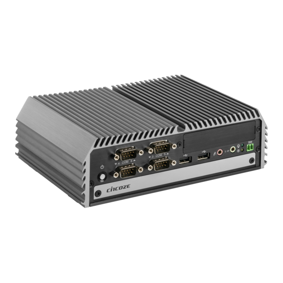
Page 14: Product Pictures
⚫ Rich I/O Including DVI, DP, 2x GbE LAN, 6x COM, 6x USB, 8x Optical Isolated DIO ⚫ Supports Cincoze CMI Technology for LAN, PoE & M12 Connector Expansion ⚫ Supports Cincoze CFM Technology for Power Ignition Sensing (IGN) Function Expansion ⚫... -
Page 15: Hardware Specification
• Storage Temperature: -40°C to 85°C Expansion • Relative Humidity: 95% RH @ 40°C (Non-condensing) • 1x CFM Interface for Cincoze CFM Modules • Shock: Operating, 50 Grms, Half-sine 11 ms Duration • 1x CMI Interfaces for Cincoze CMI Modules (w/ SSD, according to IEC60068-2-27) •... -
Page 16: System I/O
Used to inserts a SIM card block IGN Setting Switch Universal I/O Bracket Used to set up IGN function Used to customized I/O output with optional Clear CMOS Switch modules Used to clear CMOS to reset BIOS DI-1000 Series | User Manual... -
Page 17: Rear
Used to connect the system with DisplayPort input and 4 digital output monitor Antenna Hole PS/2 Port Used to install an antenna jack Used to connect the PS/2 device LAN Port Used to connect the system to a local area network DI-1000 Series | User Manual... -
Page 18: Mechanical Dimension
1.7 Mechanical Dimension Unit: mm DI-1000 Series | User Manual... - Page 19 Chapter 2 Switches & Connectors DI-1000 Series | User Manual...
-
Page 20: Location Of Switches And Connectors
2.1 Location of Switches and Connectors 2.1.1 Top View DI-1000 Series | User Manual... -
Page 21: Bottom View
2.1.2 Bottom View DI-1000 Series | User Manual... -
Page 22: Switches And Connectors Definition
COM5, COM6 RS232/ RS422/ RS485 Connector MINIPCIE1 Mini PCI-Express Socket/ MSATA Select Socket MINIPCIE2 Mini PCI-Express Socket/ MSATA Select Socket POWER1 +5V/ +12V Power Output AT_ATX1 AT/ ATX Power Mode Switch CLR_CMOS Clear RTC reset switch DI-1000 Series | User Manual... -
Page 23: Definition Of Switches
ON (Default) ON (Default) COM1 Location Function DIP3 DIP4 0V(RI) ON (Default) ON (Default) COM2 Location Function DIP5 DIP6 0V(RI) ON (Default) ON (Default) COM3 Location Function DIP7 DIP8 0V(RI) ON (Default) ON (Default) COM4 DI-1000 Series | User Manual... - Page 24 SEL 7 MODE_SEL1 Pin Defined: RTC Super CAP Function Setting: Pin Define MODE_SEL1 Switch Switch mode Function Super CAP Enable (Default) Disable CLR_CMOS: Clear CMOS Switch Definition 1-2 (Left) Normal Status (Default) 2-3 (Right) Clear CMOS DI-1000 Series | User Manual...
-
Page 25: Definition Of Connectors
46 NA 11 REFCLK- 47 NA 12 NA SMB_CLK 48 +1.5V 13 REFCLK+ PETN0/SATATN0 49 NA 14 NA SMB_DATA 50 GND 15 GND PETP0/SATATP0 51 NA 16 NA 52 +3.3V 17 NA 18 GND USB_D- DI-1000 Series | User Manual... - Page 26 46 NA 11 REFCLK- 47 NA 12 SIM_CLK SMB_CLK 48 +1.5V 13 REFCLK+ PETN1/SATATN1 49 NA 14 SIM_RESET SMB_DATA 50 GND 15 GND PETP1/SATATP1 51 NA 16 SIM_VPP 52 +3.3V 17 NA 18 GND USB_D- DI-1000 Series | User Manual...
- Page 27 Connector Type: 1X4-pin Wafer, 2.0 mm pitch Definition +12V PWR_SW2: Power On/Off, SW Switch Connector Type: Terminal Block 2X2 4-pin, 3.5mm pitch Definition PWR_SW Note: DO NOT apply power to this CONNECTOR!!! This port is used to connect a SWITCH!!! DI-1000 Series | User Manual...
- Page 28 COM1~6: RS232 / RS422 / RS485 Connector Connector Type: 9-pin D-Sub RS422 / 485 RS485 RS232 Full Duplex Half Duplex Definition Definition Definition DATA - DATA + DI-1000 Series | User Manual...
-
Page 29: Chapter 3 System Setup
Chapter 3 System Setup DI-1000 Series | User Manual... -
Page 30: Disassembling The System For Installation
1. Turn over the unit to have the bottom side face up, loosen the 6 screws on the bottom cover and place them aside for later use. 2. Remove the bottom cover from the chassis. DI-1000 Series | User Manual... - Page 31 3. Hold front and rear panel and lift up the body of unit vertically. 4. Turn over the body of the unit and place it gently. DI-1000 Series | User Manual...
-
Page 32: Installing So-Dimm Memory
1. Locate the SODIMM socket on the top side of system. 2. Tilt the SO-DIMM module at a 45-degree angle and insert it to SO-DIMM socket until the gold-pated connector of module contacted firmly with the socket. 45° DI-1000 Series | User Manual... - Page 33 3. Press the modules down until it’s fixed firmly by the two locking latches on the sides. DI-1000 Series | User Manual...
-
Page 34: Installing A Mini-Pcie/Msata Card
(Applicable for full or half size card) Locate the Mini PCIe socket on the top side of system. Insert the Mini-PCIe card at a 45-degree angle until its edge connector is connected firmly into slot. MINIPCIE1 slot MINIPCIE2 slot DI-1000 Series | User Manual... - Page 35 Press down the module and fasten two screws to secure the module. DI-1000 Series | User Manual...
-
Page 36: Installing Antennas
Caution: Installing an antenna jack greater than 9mm in diameter at left side of system will be colliding with DIO terminal block connector populated on DIO ports. For the case, please try to install the antenna at left side of system. <=9mm Terminal block connector on DIO ports DI-1000 Series | User Manual... - Page 37 3. Put on washer and fasten the nut with antenna jack. 4. Assemble the antenna and antenna jack together. 5. Attach the RF connector at another end of cable onto the module. DI-1000 Series | User Manual...
-
Page 38: Installing A Sata Hard
2. Make the bottom side of HDD face up, and place the HDD bracket on it. Ensure the direction of bracket is correct and use 4 provided screws to assemble HDD and HDD bracket together. DI-1000 Series | User Manual... - Page 39 3. Turn over the HDD bracket assembly. Connect the HDD bracket to the SATA connector and fasten the 4 screws to fix it. DI-1000 Series | User Manual...
-
Page 40: Installing The Thermal Pad
3.6 Installing the Thermal Pad 1. Please find the new thermal pad that is attached on the top cover of system. 2. Remove the protection sheet on the thermal pad. Protection sheet DI-1000 Series | User Manual... -
Page 41: Assembling The System
Note: Before assembling the system’s chassis cover, please make sure the protective film on the Thermal Pad has been removed! 3.7 Assembling the System 1. Hold front and rear panel and put the body of unit back to chassis. DI-1000 Series | User Manual... - Page 42 2. Place the bottom cover back to system. 3. Fasten the bottom cover with 6 screws. DI-1000 Series | User Manual...
-
Page 43: Installing A Sata Hard Drive At Front Side
Note: It’s advised to fasten the 2 screws manually. If fastened with an electrical screw driver, please set the torque of the driver to 2.5KgF. 2. Locate the removable HDD bay and loosen the screw. DI-1000 Series | User Manual... - Page 44 4. Make the bottom side of the HDD face up, place the HDD bracket on it. Ensure the direction of bracket is correct and use 4 provided screws to assemble HDD and HDD bracket together. DI-1000 Series | User Manual...
- Page 45 5. Align the HDD bracket assembly with the entrance of removable HDD bay. Holding the rotating arm and insert the HDD bracket until the connector of HDD contact the SATA connector firmly. 6. Place the rotating arm back and fasten the screw. DI-1000 Series | User Manual...
-
Page 46: Installing A Sim Card
3.9 Installing a SIM Card 1. Locate the SIM card slot at front side. 2. Insert a SIM card into SIM slot with the gold contacts facing up. Please pay attention to the insert orientation as illustrated. DI-1000 Series | User Manual... -
Page 47: Fastening The Cover
3.10 Fastening the Cover 1. Fasten the cover by using the two screws. 3.11 Wall Mount Brackets DI-1000 series offers wall mount that customers can install system on the wall in convenient and economical ways. DI-1000 Series | User Manual... - Page 48 1. The mounting holes are at the bottom side of system. Use provided 4 screws to fasten the bracket on each side. 2. There are 2 bracket mounting holes at left and right side for customer fix the system on the wall. DI-1000 Series | User Manual...
-
Page 49: Din-Rail Mount Brackets
3.12 DIN-Rail Mount Brackets DI-1000 series offers DIN-Rail Mount that customer can install system on the DIN Rail. Please refer to section 3.11 Wall Mount Brackets to install mounting bracket at both sides of system. Fasten 2 DIN rail mounting clips to mounting brackets on both sides with provided 4 screws as illustrated. -
Page 50: Vesa Mount
DIN rail. 3.13 VESA Mount DI-1000 series supports VESA mounting that customer can mount system with panel complying with VESA 75mm and 100 mm standard for various usage. DI-1000 Series | User Manual... - Page 51 The following picture illustrates the installation of DI-1000 series on a VESA stand. Align the 4 screw holes of VESA stand with the screw holes on bottom side of system. Fasten 4 screws to fix it. Provided below is mounted with VESA stand.
-
Page 52: Side Mount Brackets
3.14 Side Mount Brackets DI-1000 series offers Side Mount that customer can install system to the right or left side of wall to create effective of space. 1. The mounting holes are at the bottom of system. Fasten the 4 screws to fix the side mount bracket with system together. - Page 53 2. Fasten the screws through the bracket mounting hole to mount system on the wall. DI-1000 Series | User Manual...
-
Page 54: Chapter 4 Bios Setup
Chapter 4 BIOS Setup DI-1000 Series | User Manual... -
Page 55: Bios Introduction
You can use arrow keys ( ↑↓ ) to highlight the field and press <Enter> to call up the sub-menu. Then you can use the control keys to enter values and move from field to field within a sub-menu. If you want to return to the main menu, just press the <Esc >. DI-1000 Series | User Manual... -
Page 56: Main Setup
Use arrow keys to move among the items and press <Enter> to accept or enter a sub-menu. 4.2.1 System Date Set the date. Please use <Tab> to switch between date elements. 4.2.2 System Time Set the time. Please use <Tab> to switch between time elements. DI-1000 Series | User Manual... -
Page 57: Advanced Setup
■ Enable ACPI Auto Configuration Enables or disables BIOS Advanced Configuration Power Interface® (ACPI) auto configuration. ■ Enable Hibernation Enables or disables system ability to hibernate state (OS/S4 state). This option may not be effective with some OS. DI-1000 Series | User Manual... -
Page 58: Amt Configuration
Enables or disables ACPI Low Power S0 idle support. 4.3.2 AMT Configuration ■ Intel AMT Enables or disables Intel® Active Management Technology BIOS Extension. ■ Un-Configure ME Enables or disables Un-Configure-Management Engine (ME) without password. DI-1000 Series | User Manual... -
Page 59: Pch-Fw Configuration
❑ Me FW Image Re-Flash Enables or disables Me FW Image Re-Flash function. 4.3.4 F81866 Super IO Configuration Set Parameters of Serial Ports. User can Enable/Disable the serial port and Select an optimal setting for the Super IO Device. DI-1000 Series | User Manual... - Page 60 Enables or disables watch dog function. ■ Watch Dog Mode Allows to set watchdog timer unit <Sec> or <Min>. ■ Watch Dog Timer Allows you to set watchdog timer’s value in the range of 0 to 255. DI-1000 Series | User Manual...
-
Page 61: Hardware Monitor
Enables or disables wake system from S5 (soft-off state). [Disabled]: Disables wake system from S5. [Fixed Time]: Sets a fixed time (HH:MM:SS) to wake system from S5. [Dynamic Time]: Sets an increase minute(s) from current time to wake system from S5 DI-1000 Series | User Manual... -
Page 62: Serial Port Console Redirection
COM0 = Serial Port 1 COM1 = Serial Port 2 COM2 = Serial Port 3 COM3 = Serial Port 4 COM4 = Serial Port 5 COM5 = Serial Port 6 4.3.8 CPU Configuration DI-1000 Series | User Manual... -
Page 63: Sata Configuration
Allows you to select which mode SATA controller will operates. Configuration options: [AHCI], [RAID] ■ Serial ATA Port 0 ❑ Port 0 [Enabled] Enables or disables SATA Port 0. ■ Serial ATA Port 1 ❑ Port 1 [Enabled] Enables or disables SATA Port 1. DI-1000 Series | User Manual... -
Page 64: Csm Configuration
[Legacy]: Enables legacy option ROM only. ■ Storage Controls the execution of UEFI and Legacy Storage option ROM. [Do not launch]: Disables option ROM execution. [UEFI]: Enables UEFI option ROM only. [Legacy]: Enables legacy option ROM only. DI-1000 Series | User Manual... -
Page 65: Asmedia Sata Controller Configuration
4.3.12 USB Configuration ■ Legacy USB Support This item allows you to enable or disable legacy USB support. When set to [Auto], legacy USB support will be disabled automatically if no USB devices are connected. DI-1000 Series | User Manual... - Page 66 Mbps Full] Wake on LAN ❑ Enables or disables wake the system with a magic packet. ■ Blink LEDs (range 0-15 seconds) Allows you to change NIC LED blink duration in range of 0-15 seconds. DI-1000 Series | User Manual...
-
Page 67: Chipset Setup
■ Above 4GB MMIO BIOS assignment Enables or disables Above 4GB Memory Mapped IO BIOS assignment. This is disabled automatically when Aperture Size is set to 2048MB. ■ Memory Configuration This item displays detailed memory configuration in the system. DI-1000 Series | User Manual... -
Page 68: Pch-Io Configuration
Configuration options: [Auto] [Gen1] [Gen2] [Gen3]. PCI Express Root Port (Mini PCIe 2) ❑ PCI Express Root Port Enables or disables PCI Express Root Port. ❑ PCIeSpeed [Auto] Allows you to select PCI Express port speed. DI-1000 Series | User Manual... - Page 69 Allows you to specify which power state system will enter when power is resumed after a power failure (G3 state). [Always on]: Enters to power on state. [Always off]: Enters to power off state. [Keep last state]: Enters to the last power state before a power failure. DI-1000 Series | User Manual...
-
Page 70: Security Setup
This section allows users to configure BIOS security settings. 4.5.1 Administrator Password Administrator Password controls access to the BIOS Setup utility. 4.5.2 User Password User Password controls access to the system at boot and to the BIOS Setup utility. DI-1000 Series | User Manual... -
Page 71: Boot Setup
■ New Boot Option Policy Allows you to change New Boot Option Policy. Configuration options: [Default] [Place First] [Place Last]. ■ Hard Drive BBS Priority Allows you to set the order of the legacy devices in this group. DI-1000 Series | User Manual... -
Page 72: Save & Exit
■ Save as User Defaults This item allows you to save the changes done so far as user defaults. ■ Restore User Defaults This item allows you to restore the user defaults to all the setup options. DI-1000 Series | User Manual... -
Page 73: Chapter 5 Product Application (For Dio Only)
Chapter 5 Product Application (For DIO only) DI-1000 Series | User Manual... -
Page 74: Digital I/O (Dio) Application
5.1.1 Digital I/O Programming Guide 5.1.1.1 Pins for Digital I/O 1~8 Item Standard GPIO74 (Pin107) GPIO75 (Pin108) GPIO76 (Pin109) GPIO77 (Pin110) GPIO80 (Pin111) GPIO81 (Pin112) GPIO82 (Pin113) GPIO83 (Pin114) DI-1000 Series | User Manual... - Page 75 Following is an example to enable configuration and to disable configuration by using debug. -o 4e 87 -o 4e 87 (enable configuration) -o 4e aa (disable configuration) 5.1.1.3 Relative Registers To program the F81866A configuration registers, see the following configuration procedures. DI-1000 Series | User Manual...
- Page 76 DI-1000 Series | User Manual...
- Page 77 // Select logic device 06h <Output/Input Mode Selection> // Set GP80 to GP83 output Mode WriteByte(AddrPort, 0x88) // Select configuration register 88h WriteByte(DataPort, 0xXF)) // Set (bit 0~3) = 1 to select GP 80 ~83 as Output mode. DI-1000 Series | User Manual...
- Page 78 // Select configuration register 60h (High Byte address) WriteByte(DataPort, (0x0A)) WriteByte(AddrPort, 0x61) // Select configuration register 61h (Low Byte address) WriteByte(DataPort, (0x00)) <Leave the Extended Function Mode> WriteByte(AddrPort, 0xAA) Cincoze default GPIO Port base address is 0xA00h DI-1000 Series | User Manual...
- Page 79 (Base - - - - 1 0 0 0 value Base address address +3) +2) (0xA02) (0xA03) DIO I/O Port Address (Default Address 0xA00) 5.1.1.7 Pin Definition Data Bits 0xA03 0xA02 I/O Port address DI-1000 Series | User Manual...
-
Page 80: Digital I/O (Dio) Hardware Specification
DO Signal have to pull up resistor to XCOM+ for external device, the resistance will affect the pull up current Signal High Level: Pull up resistor to XCOM+ Signal Low Level: = XCOM- Sink Current: 1A (Max) DI-1000 Series | User Manual... -
Page 81: Dio Connector Definition
5.2.1 DIO Connector Definition DIO1: Digital Input / Output Connector Connector Type: Terminal Block 2X5 10-pin, 3.5mm pitch Definition Definition XCOM+ XCOM- (DC INPUT) (GND) Reference Input Circuit Reference Output Circuit DI-1000 Series | User Manual... - Page 82 Chapter 6 Optional Modules Pin Definitions and Settings DI-1000 Series | User Manual...
-
Page 83: Cmi-M12 Connector Definition And Settings
2_LAN1_2- 2_LAN1_1- 2_LAN1_3+ 2_LAN1_3- CMI-M12LAN with CFM-PoE Module Pin Definitions Connector Type: M12 A coded 8pin connector POE type: Midspan (B-Type) Definition Definition 2_LAN1_0+ 2_LAN1_0- 2_LAN1_1+ 2_LAN1_2+(Power PIN) 2_LAN1_2-(Power PIN) 2_LAN1_1- 2_LAN1_3+(Power PIN) 2_LAN1_3-(Power PIN) DI-1000 Series | User Manual... -
Page 84: Cfm-Ign Connector Definition And Settings
1 minute 5 minutes 10 minutes 30 minutes 1 hour 2 hours Reserved (0 second) 24V_12V_1: 12V / 24V Car Battery Switch Definition 1-2 (Right) 24V Car Battery Input 2-3 (Left) 12V Car Battery Input DI-1000 Series | User Manual... -
Page 85: Installing A High Speed Cmi Module
6.3 Installing a High Speed CMI Module The applicable high speed CMI modules for DI-1000 series are listed in the following table. Model No. Product Description CMI-LAN01-R12/UB071 CMI Module with 4x Intel I210-IT GbE LAN, RJ45 Port / 1x Universal Bracket... - Page 86 1. Loosen the 2 screws on front bezel to remove the cover plate. 2. Remove 4 rubber rings on M12 jacks; Penetrate M12 jacks of CMI module through the accompanying M12 I/O bracket. then fasten 4 ring hexes onto jacks as illustrated in right hand picture below. DI-1000 Series | User Manual...
- Page 87 3. Locate the CMI connector on the top side of system. 4. Insert the CMI module vertically into the female connector on system’s mainboard until it’s connected firmly. Fasten 3 screws to fix it. DI-1000 Series | User Manual...
- Page 88 5. Fasten 2 screws on front bezel. DI-1000 Series | User Manual...
-
Page 89: Installing A Cfm-Ign Power Ignition Module
6.4 Installing a CFM-IGN Power Ignition Module Locate the IGN connector on the bottom side of system. Insert IGN module vertically to the female connector on the system’s mainboard, and fasten 2 screws to fix it. DI-1000 Series | User Manual... - Page 90 © 2020 Cincoze Co., Ltd. All rights reserved. The Cincoze logo is a registered trademark of Cincoze Co., Ltd. All other logos appearing in this catalog are the intellectual property of the respective company, product, or organization associated with the logo.
Need help?
Do you have a question about the DI-1000 Series and is the answer not in the manual?
Questions and answers