Table of Contents
Advertisement
Quick Links
Advertisement
Table of Contents

Related Manuals for Horizon Hobby Tower Hobbies Beaver 1.5m


Summary of Contents for Horizon Hobby Tower Hobbies Beaver 1.5m
- Page 1 TOWA1375 ® ® INSTRUCTION MANUAL 724912 Created 06/23...
-
Page 2: Table Of Contents
NOTICE All instructions, warranties and other collateral documents are subject to change at the sole discretion of Horizon Hobby, LLC. For up- to-date product literature, visit horizonhobby.com or towerhobbies.com and click on the support or resources tab for this product. -
Page 3: Specifications
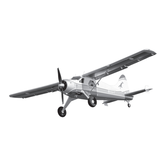
Specifications Components • Wingspan: 59.5” (1510mm) • Motor: 4011-850Kv (TOWA137516) • Length: 38.5” (980mm) • ESC: 40A, EC3 (TOWA137517) • Flying Weight: 1360-1470g • Servos: 9g, Sub-Micro (5) (TOWA137519) • Propeller: 12 x 6 (TOWA137508) • Transmitter: 6+ Channel (not included) •... -
Page 4: Assembly
Assembly The Tower DHC-2 Beaver may be assembled with either the conventional landing gear or the included floats. If installing the conventional landing gear, complete the following two steps, then skip ahead to the Horizontal Tail Installation section. If installing the floats, skip ahead to the Floats Installation section. Landing Gear Installation 1. - Page 5 Floats Installation 1. Connect the floats to each other with the horizontal struts and four M2.5x20 machine-thread screws. 2. Use eight M2.5x8 screws to fasten the braces to the floats, matching the labels printed or molded into the end of each brace to the mount location on each float.
- Page 6 3. Fasten the float braces to the fuselage with one M3x16mm screw and two M2.5x8mm screws in each side of the fuselage. No screw is installed in the third strut at this time. 4. Connect a small rubber band to the inner side of each float and water rudder as shown.
- Page 7 Horizontal Stabilizer Installation 1. Fasten the fins to each end of the horizontal stabilizer (stab) with M2x6 screws. 2. Connect the elevator pushrod to the bottom hole in the elevator horn as shown. 3. Rotate the stab upward and key it into the fuselage.
- Page 8 Vertical Stabilizer Installation 1. Key the rudder torque rod down into the receptacle while fitting the vertical stabilizer (fin) into the fuselage. Tightly press the assembly down into position. 2. Secure the horizontal and vertical stabilizers with the M3x22 screw.
- Page 9 Wing Installation 1. Fasten the wing clips to both sides of the fuselage with four M3x10 screws. 2. Guide the wires from the right wing into the fuselage, then slide the wing joiner tube and the flap pushrod wire through the corresponding holes.
- Page 10 4. Mount the left wing the same way. 5. Mount the top of each wing strut to the wing with a M2.5x8 machine-thread screw. 6. Mount the bottom of each strut to the fuselage over the third float strut (or over the main landing gear) with a M3x16 screw.
- Page 11 Receiver Installation Install your receiver on the right side of the compartment in the front of the fuselage, opposite of the electronic speed control, connecting the servos according to the labels attached to the wires. Follow the receiver manual recommendations for setup. Battery Installation The flight battery is installed in the angled middle section of the front fuselage compartment and is held in place by the included...
- Page 12 Connect the Rudder and Elevator 1. Power on the transmitter, fully lower the throttle stick, and center the trims. 2. Connect the battery to the ESC. TIP: A magnetic screwdriver, or a small magnet stuck to a screw driver to make it magnetic, will be helpful for the next couple of steps.
- Page 13 6. Repeat the same procedure for the rudder, making sure it is centered. Lock the pushrod in place on the servo arm with the screw and threadlocker. 7. Disconnect the battery and power off the transmitter. Connect the Lights, Flaps, and Ailerons 1.
- Page 14 3. Move the dial or switch on your transmitter that controls the flaps to the “up” position, rotating the flap servo arm clockwise. Remove the screw in the flap servo arm, wet the threads with threadlock, and then reinstall and tighten the screw so the flaps will be in their fully retracted (“up”) position.
-
Page 15: Control Throws
Control Throws Because the servos and pushrods are factory installed the control throws should be correct. Because of the effect the control throws have on a model, it’s always a good idea to confirm they are correct. 1. Confirm the controls respond in the correct direction according to control inputs from the transmitter. -
Page 16: Propeller And Spinner Installation
Propeller and Spinner Installation Failure to follow these safety precautions may result in severe injury to yourself and others. • Wear safety glasses whenever in the proximity of a spinning • Always stay behind the arc of the propeller when handling the propeller. -
Page 17: Center Of Gravity (Cg)
Center Of Gravity (CG) Same as the control throws, the center of gravity has a great effect on how every model flies. • If the model is tail heavy it may be unstable and respond too quickly to the controls. •... -
Page 18: Before Every Flight
Before Every Flight To help avoid flight accidents, ground inspections should be performed prior to every flight. • Ensure all screws are secure, the servo arms and horns are • After the aircraft is powered on, perform a control surface check properly connected and the wing is properly secured. -
Page 19: Repairs
Repairs Parts damaged beyond repair can be purchased separately. Often parts can be repaired and you can get your Beaver back into the air with a little glue and ingenuity. The Beaver is made from injection-molded EPO (expanded polyolefin) foam which can be glued with just about anything. Most people use regular CA. -
Page 20: Replacement Parts
Replacement Parts Part # Description Part # Description TOWA137501 Fuselage: DHC-2 Beaver 1.5m TOWA137520 Wing Strut Set: DHC-2 Beaver 1.5m TOWA137502 Wing Set: DHC-2 Beaver 1.5m TOWA137521 Decal Set: DHC-2 Beaver 1.5m TOWA137503 Horizontal Stabilizer: DHC-2 Beaver 1.5m TOWA137522 Servo Arm Set: DHC-2 Beaver 1.5m TOWA137504 Vertical Stabilizer: DHC-2 Beaver 1.5m TOWA137523... -
Page 21: Limited Warranty
What this Warranty Covers questions and service you in the event that you may need any Horizon Hobby, LLC, (Horizon) warrants to the original purchaser assistance. For questions or assistance, please visit our website that the product purchased (the “Product”) will be free from at www.horizonhobby.com, submit a Product Support Inquiry,... -
Page 22: Warranty And Service Contact Information
Class B digital device, pursuant to part • Consult the dealer or an experienced radio/TV technician for help. 15 of the FCC Rules. These limits are designed to provide Horizon Hobby, LLC reasonable protection against harmful interference in a 2904 Research Road residential installation. - Page 24 ©2023 Horizon Hobby, LLC. Tower Hobbies, the Tower Hobbies logo, and the Horizon Hobby logo are trademarks or registered trademarks of Horizon Hobby, LLC. The Spektrum trademark is used with permission of Bachmann Industries, Inc. All other trademarks, service marks and logos are property of their respective owners. US 8,672,726 US 9,056,667 http://www.horizonhobby.com/...
Need help?
Do you have a question about the Tower Hobbies Beaver 1.5m and is the answer not in the manual?
Questions and answers