Table of Contents
Advertisement
Available languages
Available languages
Quick Links
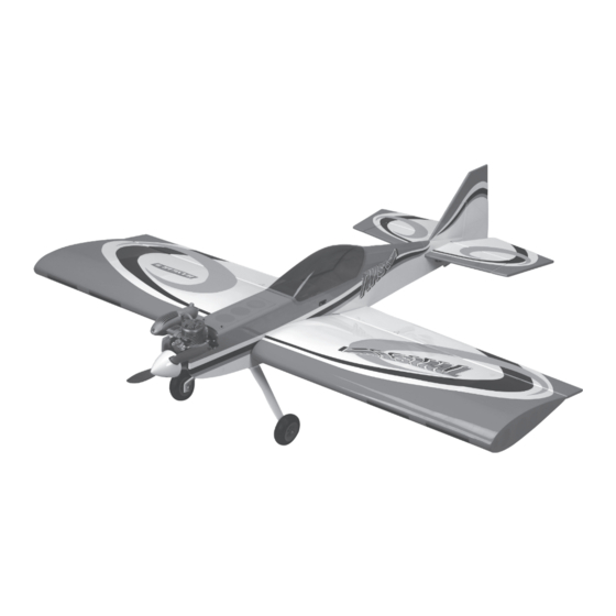
Twist 60 ARF
Instruction Manual
Manuel d'utilisation
Scan the QR code and select the Manuals and Support quick links from the product
page for the most up-to-date manual information.
Scannez le code QR et sélectionnez les liens rapides Manuals and Support sur la
page du produit pour obtenir les informations les plus récentes sur le manuel.
HAN4210
Created 12/2022
Advertisement
Chapters
Table of Contents

Related Manuals for Horizon Hobby HANGAR 9 Twist 60 ARF


Summary of Contents for Horizon Hobby HANGAR 9 Twist 60 ARF
- Page 1 Twist 60 ARF Instruction Manual Manuel d’utilisation Scan the QR code and select the Manuals and Support quick links from the product page for the most up-to-date manual information. Scannez le code QR et sélectionnez les liens rapides Manuals and Support sur la page du produit pour obtenir les informations les plus récentes sur le manuel.
-
Page 2: Notice
Horizon Hobby, LLC. This manual contains instructions for safety, operation and maintenance. It is essential to read and follow all the instructions and warnings in the manual, prior to assembly, setup or use, in order to operate IMPORTANT FEDERAL AVIATION ADMINISTRATION (FAA) INFORMATION correctly and avoid damage or serious injury. -
Page 3: Table Of Contents
TABLE OF CONTENTS SPECIFICATIONS Notice ..................................2 Wingspan 54.75 in (1391mm) Meaning of Special Language ..........................2 Length 56.6 in (1438mm) Safety Warnings and Precautions ..........................2 Safe Operating Recommendations ...........................2 Weight 6.5–7.5 lb (2.9kg–3.4kg) Before Starting Assembly ............................2 Engine .60–.75 2-stroke, .91–1.00 4-stroke Important Federal Aviation Administration (FAA) Information ..................2 Motor Electric Power: E-Flite Power 60... -
Page 4: Required For Completion, Two-Stroke Power Option
REQUIRED FOR COMPLETION, TWO-STROKE POWER OPTION TOOLS REQUIRED # Required Item # Description Description APC12060 Sport Propeller, 12 x 6 Adjustable wrench GEA2S2400RXJS 7.6V 2400 mAh 2s, RX, LiPo JST Drill OSMG0557 55AX ABL .55 Airplane Glow Engine w/ Muffler Drill bit set, metric or english SPM9532 Deluxe 3-Wire Switch Harness... -
Page 5: Removing Wrinkles
REMOVING WRINKLES AILERON SERVO INSTALLATION The covering of your model may develop wrinkles during shipping. Use a covering iron with a sealing iron sock Required Parts (HAN141) to remove them. Start with a lower heat setting and use caution while working around areas where the •... - Page 6 Prepare an aileron servo by installing the grommets and Enlarge the outer hole of the servo arm using a 5/64” (2mm) brass eyelets provided with the servo. Secure a 9” (228mm) drill bit. Remove the pushrod keeper from the linkage and servo extension to the servo using a commercially available slide the bend to the servo arm.
-
Page 7: Landing Gear And Tail Installation
LANDING GEAR AND TAIL INSTALLATION Slide the rudder/stabilizer onto the fuselage. Guide the threaded rods through the stabilizer saddle then through the Required Parts holes in the bottom of the fuselage. • Landing gear w/wheels • Fuselage • 1” (25mm) tail wheel •... -
Page 8: Two-Stroke Engine Installation
Repeat Steps 6 and 7 to install the elevator servo and linkage. TWO-STROKE ENGINE INSTALLATION Position the engine on the engine mount so the drive washer is 5” (127mm) ahead of the firewall. Mark the location of the Required Parts engine mounting bolts using a felt-tipped pen. - Page 9 10. Use a hobby knife to remove the covering over the hole in Install the muffler onto your engine using the instructions provided with the engine as a guide. the rear of the fuselage hatch for the 4-40 screw. Place the fuselage hatch into position and secure it using the 4-40 x 1/2”...
-
Page 10: Electric Motor Installation
ELECTRIC MOTOR INSTALLATION Attach the motor to the firewall using the four 2” (51mm) aluminum motor spacers, four 8-32 x 2 ” machine screw Required Parts and four 8-32 blind nuts. Use the holes that are closer to • Fuselage •... -
Page 11: Final Assembly
FINAL ASSEMBLY Remove the covering from the bottom of the fuselage to allow for cooling air through the fuselage. Required Parts • Fuselage • Wing • 1/4-20 x 1 ” nylon bolt (2) • Canopy Required Tools and Adhesives • Canopy glue •... -
Page 12: Center Of Gravity
CENTER OF GRAVITY Mount the switch harness in the side of the fuselage. The switch should be on the opposite side of the muffler when using a glow engine. CAUTION: You must adjust your aircraft’s center of gravity and balance your model properly before attempting flights. An important part of preparing the aircraft for flight is properly balancing the model. -
Page 13: Control Throws
7/8 inches (22 mm) misuse, abuse, negligence, commercial use, or due to improper use, installation, operation or maintenance, (iii) modification of or to any part of the Product, (iv) attempted service by anyone other than a Horizon Hobby authorized inches (70mm) -
Page 14: Warranty And Service Contact Information
Union D 22885 Barsbüttel, Germany Sales: Horizon Hobby GmbH +49 (0) 4121 2655 100 where you can be reached during business hours. When sending product into Horizon, please include your RMA number, a list of the included items, and a brief summary of the problem. A copy of your original sales receipt must be included for warranty consideration. -
Page 15: Academy Of Model Aeronautics National Model Aircraft Safety Code
ACADEMY OF MODEL AERONAUTICS NATIONAL MODEL AIRCRAFT SAFETY CODE BUILDING NOTES Effective January 1, 2018 A model aircraft is a non-human-carrying device capable of sustained flight within visual line of sight of the pilot or spotter(s). It may not exceed limitations of this code and is intended exclusively for sport, recreation, education and/or competition. -
Page 16: Remarque
être utilisé par des enfants sans la surveillance directe d’un adulte. N’essayez pas de modifier ou d’utiliser ce produit • Nous vous recommandons d’affecter maintenant le récepteur à l’émetteur en suivant les instructions fournies avec avec des composants incompatibles hors des instructions fournies par Horizon Hobby, LLC. Ce manuel comporte des votre radio. -
Page 17: Spécifications
TABLE DES MATIÈRES SPÉCIFICATIONS Remarque ................................16 Envergure d’aile 1391 mm (54,75 po) Signification de certains termes spécifiques ......................16 Longueur 1438mm (56,6 po) Avertissements relatifs à la sécurité ........................16 Consignes de sécurité concernant l’utilisation ......................16 Poids 2,9 kg-3,4 kg (6,5-7,5 lb) Avant de commencer l’assemblage ........................16 Moteur 0,60- 0,75 2 temps, 0,91-1,00 4 temps Spécifications ................................17... -
Page 18: Requis Pour La Finition, Option Puissance À Deux Temps
REQUIS POUR LA FINITION, OPTION PUISSANCE À DEUX TEMPS OUTILS NÉCESSAIRES Nombre Pièce Description Description requis Clé ajustable APC12060 Hélice 12 x 6 Competition Mini-perceuse GEA2S2400RXJS 7,6 V 2400 mAh 2s, RX, LiPo JST Ensemble de mèches, impériales ou métriques OSMG0557 Moteur thermique d’avion 55AX ABL .55 avec silencieux Pinceau Epoxy SPM9532 Faisceau de commutateur à... -
Page 19: Retrait Des Faux-Plis
RETRAIT DES FAUX-PLIS INSTALLATION DU SERVO DE L’AILERON Des faux-plis peuvent se former sur l’entoilage de votre modèle pendant l’expédition. Utilisez un fer d’entoilage avec Pièces nécessaires une chaussette de fer d’étanchéité (HAN141) pour les retirer. Commencez avec une température peu élevée, puis faites •... - Page 20 Préparez un servo d’aileron en installant les passe-fils et les Élargissez l’orifice extérieur du bras du servo à l’aide d’une œillets en laiton fournis avec le servo. Fixez une rallonge de mèche de 2 mm (5/64 po). Retirez la butée de barre de liaison servo de 228 mm (9 po) au servo à...
-
Page 21: Installation Du Train D'atterrissage Et De La Queue
INSTALLATION DU TRAIN D’ATTERRISSAGE ET DE Faites glisser la gouverne de direction/le stabilisateur sur le fuselage. Faites passer les tiges filetées dans le pontet du LA QUEUE stabilisateur puis dans les orifices du bas du fuselage. Pièces nécessaires • Train d’atterrissage avec roues •... -
Page 22: Installation Du Moteur À Deux Temps
Répétez les étapes 6 et 7 pour installer le servo de la gouverne de profondeur et la tringlerie. INSTALLATION DU MOTEUR À DEUX TEMPS Placez le moteur sur le support moteur de façon à ce que la rondelle d’entraînement soit à 127 mm (5 po) en avant Pièces nécessaires du pare-feu. - Page 23 10. À l’aide d’un couteau, retirez l’entoilage qui recouvre l’orifice Installez le silencieux sur votre moteur en suivant les instructions fournies avec le moteur comme guide. de la vis 4-40 à l’arrière de la trappe du fuselage. Placez la trappe du fuselage en position et fixez-la à l’aide de la vis à pans creux 4-40 x 13 mm (1/2 po).
-
Page 24: Installation Du Moteur Électrique
INSTALLATION DU MOTEUR ÉLECTRIQUE Fixez le moteur au pare-feu à l’aide des quatre entretoises de moteur en aluminium de 51 mm (2 po), de quatre vis Pièces nécessaires mécaniques 8-32 x 64 mm (2 po) et de quatre écrous • Fuselage borgnes 8-32. Utilisez les orifices les plus proches de l’ouverture du pare-feu pour fixer le moteur. -
Page 25: Assemblage Final
ASSEMBLAGE FINAL Retirez l’entoilage de la partie inférieure du fuselage pour permettre à l’air de refroidissement de passer à travers le Pièces nécessaires fuselage. • Fuselage • Aile • Boulons en nylon 1/4-20 x 38 mm (1 po) (2) • Verrière Outils et adhésifs nécessaires •... -
Page 26: Entre De Gravité
ENTRE DE GRAVITÉ Montez le faisceau du commutateur sur le côté du fuselage. Le commutateur doit se trouver du côté opposé au silencieux si vous utilisez un moteur thermique. ATTENTION : vous devez ajuster le centre de gravité de votre appareil et équilibrer correctement votre modèle avant le vol. -
Page 27: Débattements
Mettez l’émetteur et le récepteur de votre maquette sous tension. Vérifiez le mouvement de la dérive à l’aide Garantie exclusive - Horizon Hobby, LLC (Horizon) garantit que le Produit acheté (le « Produit ») sera exempt de défauts de l’émetteur. Lorsque le manche se déplace vers la droite, la dérive doit également se déplacer vers la droite. -
Page 28: Coordonnées De Garantie Et Réparations
Les demandes en garantie seront uniquement traitées en présence d’une preuve d’achat originale émanant d’un revendeur spécialisé agréé, sur laquelle figurent le nom de l’acheteur ainsi que la date d’achat. Si le cas de garantie est confirmé, le produit sera réparé. Cette décision relève uniquement d’Horizon Hobby. Réparations payantes En cas de réparation payante, nous établissons un devis que nous transmettons à... - Page 29 ASSEMBLY NOTES • NOTES RELATIVES AU MONTAGE Christen Eagle II 90 ARF...
- Page 30 ASSEMBLY NOTES • NOTES RELATIVES AU MONTAGE...
- Page 31 ASSEMBLY NOTES • NOTES RELATIVES AU MONTAGE Christen Eagle II 90 ARF...
- Page 32 © 2023 Horizon Hobby, LLC. Hangar 9, Evolution, JR, DSM2, DSMX, PowerPro, EC3, UltraCote and the Horizon Hobby logo are trademarks or registered trademarks of Horizon Hobby, Inc. The Spektrum trademark is used with permission of Bachmann Industries, Inc. All other trademarks, service marks and logos are the property of their respective owners.
Need help?
Do you have a question about the HANGAR 9 Twist 60 ARF and is the answer not in the manual?
Questions and answers