
Related Manuals for Horizon Hobby E-flite PLATINUM DHC-2 Beaver ARF


Summary of Contents for Horizon Hobby E-flite PLATINUM DHC-2 Beaver ARF
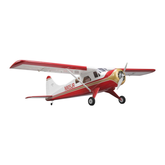
- Page 1 DHC-2 Beaver ARF Assembly Manual Specifications Wingspan: 68 in (1735mm) Length: 43 in (1090mm) Wing Area: 565 sq in (36.4 sq dm) Weight w/ Battery: 4.9–6.2 lb (2.2–2.8 kg) Weight w/o Battery: 4–4.25 oz (1.8–1.9 kg)
-
Page 2: Table Of Contents
Table of Contents Introduction Specifications ..............1 The full-scale DHC-2 Beaver was originally intended for flight in Introduction ................. 2 areas of remote wilderness. Designed to be particularly durable Platinum Series Statement ............ 2 and powerful, the Beaver could easily be fitted with wheels, skis Using the Manual .............. -
Page 3: Using The Manual
Using the Manual Small parts: EFL4529 Cowling This manual is divided into sections to help make assembly EFL4530 Window Set easier to understand, and to provide breaks between each EFL4531 Landing Gear major section. In addition, check boxes have been placed next EFL4532 Battery Hatch to each step to keep track of each step completed. -
Page 4: Required Radio Equipment
Required Radio Equipment Important Information About Motor Selection You will need a minimum 6-channel transmitter (for proper We recommend the E-flite ® Power 25 Brushless Outrunner, mixing and dual rate capabilities), crystals, receiver, and six mini servos. You can choose to purchase a complete radio system. 870Kv (EFLM4025A) or the E-flite Power 32 Brushless Outrunner, 770Kv (EFLM4032A) if you plan on flying with the If you are using an existing transmitter, just purchase the other... -
Page 5: Optional Accessories
Optional Accessories Pencil Phillips screwdriver: #1, #2 EFLA110 Power Meter Pin drill EFL4537 Cockpit Kit Rotary tool w/sanding drum EFLA151 Pilot Bust Ruler EFLA500 25-Size Fiberglass Floats Sandpaper EFLAEC303 EC3 Device & Battery Connector, Side cutters Male/Female Thin CA EFLC3005 Celectra 1- to 3-Cell Li-Po Charger Threadlock EFLC505... -
Page 6: Notes Regarding Servos And Esc
WARNING: Use of servos other than those we recommend may overload the BEC of the recommended Electronic Speed Control Horizon Hobby, Inc., (Horizon) warranties that the Products purchased (ESC). We suggest the use of only the servos we recommend (the “Product”) will be free from defects in materials and workmanship at the date of purchase by the Purchaser. - Page 7 Provided warranty conditions have been met, your Product will be repaired or replaced free of charge. Repair or replacement decisions are at the sole discretion of Horizon Hobby. E-flite DHC-2 Beaver ARF Assembly Manual...
-
Page 8: Safety, Precautions, And Warnings
Safety, Precautions, and Warnings Non-Warranty Repairs Should your repair not be covered by warranty the repair As the user of this product, you are solely responsible for will be completed and payment will be required without operating it in a manner that does not endanger yourself notification or estimate of the expense unless the expense and others or result in damage to the product or the property exceeds 50% of the retail purchase cost. -
Page 9: Landing Gear Installation
Landing Gear Installation 2. Secure the left half of the landing gear using two 6-32 x 3/8-inch socket head screws and two Required Parts #6 washers. Use a 7/64-inch ball driver to tighten the screws. Fuselage Landing gear (right and left) 6-32 x 3/8-inch socket head screw (4) #6 washer (4) Required Tools and Adhesives... -
Page 10: Motor And Cowling Installation
Motor and Cowling Installation 3. Secure the right half of the landing gear using two 6-32 x 3/8-inch socket head screws and Required Parts two #6 washers. Fuselage Motor w/mount and accessories #4 washer (8) Cowling Hook and loop tape (2) Motor battery Electronic speed control Propeller... - Page 11 1. Attach the X-Mount to the motor using the screws 2b. Attach the Power 25 motor to the firewall using four provided with the motor and a #2 Phillips screwdriver. 4-40 x 1/2-inch socket head screws and four #4 Make sure to use threadlock on all four screws so they washers.
- Page 12 3. Use hook and loop tape to mount the speed control to in the center of the dummy radial engine. Use a hobby the front of the battery box as shown. You will need to knife to remove the area between each of the cylinders to attach a 9-inch extension onto the ESC plug to route it to allow cooling air to pass through the cowling and over the receiver.
- Page 13 6. Attach the cowl to the fuselage using four 4-40 x 7. Insert the propeller adapter into the spinner backplate. 3/8-inch socket head screws and four #4 washers. It may be necessary to enlarge to hole in the backplate to Note the direction of the cowl as shown in the photo.
- Page 14 9. Secure the spinner cone to the backplate with the 10. Carefully remove the hatch from the bottom of the screws provided with the spinner. Use a #1 Phillips fuselage. It is held at the rear with two magnets. To open screwdriver to tighten the two screws.
- Page 15 11. Install the battery in the fuselage using the two velcro 12. You may elect to cut a hole for exit air in the aft straps. The battery can be moved forward or rearward area of your fuselage. You will notice we have designed to correct for the Center of Gravity if necessary.
-
Page 16: Aileron And Flap Servo Installation
Aileron and Flap Servo Installation 2. Use 6-minute epoxy to glue the servo mounting block to the servo cover as shown. Allow the epoxy to Required Parts fully cure before proceeding. Wing panel (right and left) Aileron servo cover (right and left) Servo mounting blocks (8) Nylon clevis (4) Clevis retainer (4) - Page 17 3. Position the servo between the servo mounting block. Use a pencil to mark the locations for the servo mounting screws on the blocks. The servo should not touch the cover to prevent it from absorbing vibrations from the airframe. You may have to notch the servo block to allow access for the servo wire.
- Page 18 6. Use a #1 Phillips screwdriver to install the screws 7. Remove any of the unnecessary arms from the provided with the servos to attach the servo to the servo horn using side cutters. Enlarge the outer hole servo mounting blocks.
- Page 19 9. Tie the string to the servo extension and pull it to the 10. Secure the aileron servo cover to the wing opening for the flap servo at this time. using four #2 x 3/8-inch sheet metal screws and a #1 Phillips screwdriver.
- Page 20 12. Slide a clevis retainer onto a nylon clevis. With the 14. Prepare the flap servos for installation by removing aileron servo centered using the radio, thread the clevis any unnecessary arms from the servo horns as shown. onto the pushrod.
- Page 21 15. Using a ruler, mark the servo cover as shown 17. Secure a 3-inch (76mm) extension to the flap servo using a pencil. lead. Tie the string to the flap servo extension and pull both the aileron and flap leads to the hole in the bottom of the wing.
- Page 22 18. Slide the bend of the 2 -inch (58mm) pushrod into 19. Position the flap servo partially in the wing. Connect the hole of the flap servo. Secure the pushrod using the the clevis to the flap control horn. Plug the flap servo into pushrod connector.
- Page 23 Note: Do not place or secure the flap servo cover in 21. Secure the flap servo cover to the wing using position before turning on the radio and checking the four #2 x 3/8-inch sheet metal screws and a operation of the flap.
-
Page 24: Joining The Wing Panels
Joining the Wing Panels 2. Slide the wing joiner into the wing panel. Use a pencil to mark the joiner against the wing. The joiner should fit Required Parts snug in the wing. If it does not fit, lightly sand the joiner until it does fit nicely. - Page 25 Note: The following steps will be performed while 5. Coat the root rib of the wing panel with epoxy. Apply you have epoxy mixed. Make sure the steps can epoxy into the opening for the joiner as well. be performed before the epoxy begins to cure. It is suggested to make a test run of the steps if you are unsure of the procedure.
- Page 26 7. Use low-tack tape to hold the two wing panels tightly 8. Using a trim iron, iron on the piece of white ultra cote together until the epoxy fully cures. to seal the wing joint. Note: You may use rubbing alcohol and paper towels to clean up any epoxy that might have spilt on the wings during this process before the epoxy hardens.
-
Page 27: Rudder And Elevator Installation
Rudder and Elevator Installation 2. Attach the wing to the fuselage using a flat blade screwdriver and the two nylon wing bolts. Required Parts Fuselage Rudder/fin assembly Stabilizer/elevator assembly Rudder control horn Tail wheel assembly Tail wheel control horn Nylon wing bolt (2) Wing strut (2) Wing assembly... - Page 28 4. Slide the stabilizer into position. Center the stabilizer 6. Check the alignment between the wing and stabilizer. as shown in the photo. They should be parallel to each other. If not, lightly sand the stabilizer saddle until the wing and stabilizer are in alignment with each other.
- Page 29 8. Use a sharp hobby knife to cut the covering slightly 9. Slide the stabilizer back into position. After checking inside the lines drawn. Be very careful not to cut into the the alignment, wick thin CA into the joint between the underlying wood, as this will weaken the stab and cause fuselage and stabilizer on both the top and bottom of it to fail in flight.
- Page 30 10. Insert the rudder control rod into the fuselage, then 11. Use a felt-tipped pen to trace the outline of the slide the fin into the slot in the top of the fuselage. fuselage onto the fin. Also trace the outline of the dorsal fin onto the top of the fuselage.
- Page 31 12. Use a sharp hobby knife to cut the covering 13. Check that the fin is square to the stabilizer. Sanding slightly below the lines drawn. Be very careful not to the bottom of the fin where it fits into the fuselage can cut into the underlying wood, as this will weaken the fin correct for any alignment issues.
- Page 32 14. Slide the fin up slightly so the rudder control horn 15. Wick thin CA into the joint between the fuselage can be installed on the rudder control rod. Use a setscrew and fin. Make sure the fin is glued into the slot in the and the provided hex wrench to tighten the setscrew on fuselage, as well as to the top of the fuselage.
-
Page 33: Radio Installation
Radio Installation 2. Remove the two arms (front and rear) from the servo horn using side cutters. Required Parts Fuselage assembly Servo w/hardware (2) Brass pushrod connector Connector backplate Clevis (3) Clevis retainer (3) Pushrod connector (2) 3mm setscrew Hook and loop material Receiver -inch (606mm) pushrod wire... - Page 34 5. Repeat Steps 1 and 2 to prepare the elevator servo. 4. Secure the connector using the connector backplate. 6. Place the elevator servo into the fuselage with the output facing to the front. Use a pin drill and 1/16-inch (1.5mm) drill bit to drill the holes for the Note: If you are installing floats, prepare the rudder servo mounting screws.
- Page 35 7. Place 2–3 drops of thin CA into each of the holes to 9. Repeat Steps 6 through 8 to install the rudder servo. harden the surrounding wood. This hardens the wood and provides a better bite for the screws. 10.
- Page 36 11. Slide a clevis retainer onto a nylon clevis. Thread the 13. Slide the pushrod into the hole in the servo horn and clevis about 14 turns on the rudder pushrod. The exact secure it using a pushrod connector. position will be adjusted later in the manual.
- Page 37 Note: If you are planning on installing floats, skip Steps 15. Repeat Steps 11 through 14 to install the 24 -inch 16 and 17 as they pertain to the installation of the tail (631mm) elevator pushrod wire. wheel linkage. 16.
- Page 38 17. After centering the tail wheel, tighten the 3mm 18. Install the tail cone using the screws that setscrew to secure the pushrod. Use this connection to were removed earlier in the manual and a trim the steering of your Beaver on the ground. DO NOT #1 Phillips screwdriver.
-
Page 39: Optional Float Installation
Optional Float Installation 19. Use hook and loop tape to secure the receiver inside the fuselage. If you are using a remote receiver, secure it Required Parts as far away and as far up in the fuselage as possible. Fuselage assembly Float set w/hardware Beaver float mount (included with kit) - Page 40 2. With the float supports resting on your work surface, 3. Position the strap for the float mount at the corner use the supplied hex wrench to tighten the four setscrews of the battery tray as shown. It should be as close as to secure the braces in position.
- Page 41 4. Attach the float mount to the bottom of the fuselage 6. Using threadlock, tighten the setscrews for the cross using two straps, four 3mm x 12mm sheet metal screws braces on the float mount. Assemble and attach the floats and a #2 Phillips screwdriver.
- Page 42 7. Drill a 1/8-inch (3mm) hole in the bottom of the 8. Connect the pushrod cable to the connector. The fuselage near the landing gear. Route the float pushrod pushrod must be secured inside the fuselage. Wrap string through the hole and into the fuselage.
- Page 43 Windows, Cockpit and 2. Test fit the forward cockpit floor in the fuselage. Trim the floor as necessary using hobby scissors. The cockpit Air Scoop Installation floor is then glued in using medium CA. Required Parts Fuselage assembly Cockpit kit (optional) Side window set Front windscreen Air scoop (2)
- Page 44 3. Remove the backing from the adhesive strips on the 5. Use canopy glue to secure the right and left front side bottom of the seat backs. Attach the seat backs to the windows to the inside of the fuselage. forward cockpit floor.
- Page 45 7. Use canopy glue to attach the front windscreen to the 8. Use medium CA to glue the rear cockpit floor blocks fuselage. Scuff the covering and windscreen where they to the sides of the fuselage slightly below the level of the contact each other using fine sandpaper to provide a center side window.
- Page 46 10. Secure the rear cockpit floor in the fuselage using 11. Trim the center and rear side windows from the four #2 x 3/8-inch sheet metal screws. The screws will go window set using hobby scissors and a hobby knife. through the rear cockpit floor and into the block installed in Step 8.
-
Page 47: Control Throws
Control Throws 13. Use medium CA to glue the air scoops to the fuselage using the images below and those on the box as guides. 1. Turn on the transmitter and receiver of your DHC-2 Beaver. Check the movement of the rudder using the transmitter. When the stick is moved right, the rudder should also move right. -
Page 48: Range Test Your Radio
Range Test Your Radio Ailerons Low Rate: 1/2-inch (13mm) (Up/Down) 1. Please consult your radio instructions for complete range High Rate: 3/4-inch (19mm) (Up/Down) testing instructions. 2. Double-check that all controls (aileron, elevator, rudder Elevator and throttle) move in the correct direction. Low Rate: 5/8-inch (16mm) (Up/Down) ... -
Page 49: Center Of Gravity
Center of Gravity Preflight An important part of preparing the aircraft for flight is properly Check Your Radio balancing the model. Before going to the field, be sure that your batteries are fully charged per the instructions included with your radio. Charge Caution: Do not inadvertently skip this step! both the transmitter and receiver pack for your airplane. -
Page 50: Flying Your Dhc-2 Beaver Arf
Flying Your DHC-2 Beaver ARF be either landed on the mains or three pointed on the gear in a full stall. The choice is yours. Landing without using flaps is You will find the Beaver to be a very docile model in the air no different, just a bit faster on the final approach, but very and on the ground. -
Page 51: 2008 Official Ama National Model Aircraft Safety Code
2008 Official AMA National 4) I will operate my model using only radio control frequencies currently allowed by the Federal Communications Commission. Model Aircraft Safety Code (Only properly licensed Amateurs are authorized to operate equipment on Amateur Band frequencies.) GENERAL 5) Flying sites separated by three miles or more are considered safe 1) I will not fly my model aircraft in sanctioned events, air shows from site-to-site interference, even when both sites use the same... - Page 52 © 2008 Horizon Hobby, Inc. 4105 Fieldstone Road Champaign, Illinois 61822 (877) 504-0233 horizonhobby.com E-fliteRC.com 12403.1...
Need help?
Do you have a question about the E-flite PLATINUM DHC-2 Beaver ARF and is the answer not in the manual?
Questions and answers