Table of Contents
Advertisement
Advertisement
Chapters
Table of Contents

Related Manuals for Upright SL26SL


Summary of Contents for Upright SL26SL
- Page 1 SL26/30SL WORK PLATFORM...
- Page 3 Serial Numbers 50001 – Current NGLISH When contacting UpRight for service or parts information, be sure to include the MODEL and SERIAL NUMBERS from the equipment nameplate. Should the nameplate be missing, the SERIAL NUMBER is also stamped on top of the chassis above the front axle pivot.
- Page 4 SL26/30SL S ERVICE AND ARTS ANUAL : 505500-000 (04-07) UMBER : 50000 - C ERIAL UMBER URRENT OREWORD OW TO ANUAL This manual is divided into six sections. NTRODUCTION ECTION General description and machine specifications. PERATION AND PECIFICATION ECTION Information on how to operate the work platform and how to prepare it for operation. AINTENANCE ECTION Preventative maintenance and service information.
- Page 5 Please understand that these warnings cannot cover all conceivable ways in which service, whether or not recommended by Upright, might be carried out, or of the possible hazardous consequences of each conceivable way, nor could Upright, investigate all such ways.
- Page 6 URPOSE The purpose of this service and parts manual is to provide instructions and illustrations for the operation and maintenance of this work platform manufactured by UpRight. COPE The manual includes procedures for proper operation, maintenance, adjustment, and repair of this product as well as recommended maintenance schedules and troubleshooting.
- Page 7 Introduction HASSIS The chassis is a structural frame that supports all the components of the SL26/30SL work plat- form. URPOSE OF QUIPMENT The objective of the work platform is to provide a quickly deployable, self-propelled, variable height work platform to elevate personnel and materials to overhead work areas. PECIAL IMITATIONS Travel with the platform raised is limited to a creep speed range.
- Page 9 PERATION ANUAL WARNING All personnel shall carefully read, understand and follow all safety rules and operating instructions before operating or performing maintenance on any UpRight aerial work platform. Safety Rules Electrocution Hazard Tip Over Hazard Collision Hazard Fall Hazard NEVER elevate the platform or drive...
-
Page 10: Table Of Contents
ONTENTS Introduction ................3 General Description . -
Page 11: Introduction
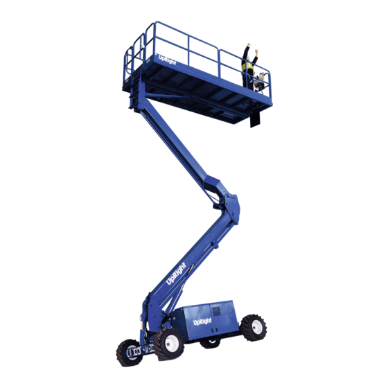
Introduction NTRODUCTION This manual covers operation of the SL26/30 Speed Level Series Self-Propelled Work Platforms. This manual must be stored on the machine at all times. ENERAL ESCRIPTION Figure 1: SL26/30 SL Series 1. Platform W A R N I N G DO NOT use the maintenance platform without guardrails properly assembled and in place... -
Page 12: Special Limitations
Special Limitations PECIAL IMITATIONS Travel with the platform raised is limited to creep speed range. Elevating the Work Platform is limited to firm, level surfaces only. D A N G E R The elevating function shall ONLY be used when the work platform is leveled and on a firm surface. The work platform is NOT intended to be driven over uneven, rough, or soft terrain. -
Page 13: Controls And Indicators
Controls and Indicators ONTROLS AND NDICATORS Figure 2: Controls and Indicators Platform Controls 1 Drive (Hi Speed) 2. Drive (Low Speed) 3. Level 4. Horn Button 5. Lift/Lower Button 6. Glow Plug 7. Engine Start 8. Emergency Stop Button 9. Display 10. -
Page 14: Pre-Operation Safety Inspection
Pre-Operation Safety Inspection PERATION AFETY NSPECTION NOTE: Carefully read, understand and follow all safety rules, operating instructions, labels and National Safety Instructions/Requirements. Perform the following steps each day before use. 1. Open modules and inspect for damage, fluid leaks or missing parts. Figure 3: Hydraulic Tank 2. -
Page 15: System Function Inspection
System Function Inspection YSTEM UNCTION NSPECTION Refer to Figure 2 (Page 5) for the locations of various controls and indicators. W A R N I N G STAND CLEAR of the work platform while performing the following checks. Before operating the work platform, survey the work area for surface hazards such as holes, drop-offs, bumps and debris. -
Page 16: Operation
Operation PERATION Before operating the work platform, ensure that the Pre-Operation Safety Inspection has been completed and that any deficiencies have been corrected. Never operate a damaged or malfunctioning machine. The operator must be thoroughly trained on this machine. T A R T I N G T H E N G I N E 1. -
Page 17: Travel With The Platform Elevated
Operation R A V E L I T H T H E L A T F O R M L E V A T E D NOTE: The machine will travel at reduced speed when the platform is elevated. 1. Check that the route is clear of obstacles (persons, obstructions, holes, drop-offs, bumps, and debris), is level, and is capable of supporting the wheel loads. -
Page 18: Emergency Lowering
Operation M E R G E N C Y O W E R I N G Figure 4: Emergency Lowering Valve W A R N I N G If the platform should fail to lower, NEVER climb down the elevating assembly. Stand clear of the elevating assembly while Emergency Lowering Knob operating the Emergency Lowering Valve... -
Page 19: Fold Down Guardrails
Operation O L D O W N G U A R D R A I L S This procedure applies only to the SL26/30 Speed Level model for the purpose of passing through a stan- dard double doorway. Guardrails must be returned to proper position before using the machine. ROCEDURE 1. -
Page 20: Towing Or Winching
Towing or Winching OWING OR INCHING Perform the following only when the machine will not operate under its own power and it is necessary to move the machine or when winching onto a transport vehicle (see “Transporting the Work Platform” on page 13). -
Page 21: Transporting The Work Platform
Transporting the Work Platform RANSPORTING THE LATFORM R E P A R A T I O N F O R H I P M E N T 1. Fully lower the platform. 2. Disconnect the battery negative (-) lead from the battery terminal. 3. -
Page 22: Maintenance
Maintenance AINTENANCE W A R N I N G Never perform service while the platform is elevated without first blocking the elevating assembly. DO NOT stand in the elevating assembly area while deploying or storing the brace. Figure 6: Scissor Brace L O C K I N G L E V A T I N G S S E M B L Y... -
Page 23: Battery Maintenance
Battery fluid is highly corrosive. Thoroughly rinse away any spilled fluid with clean water. Always replace batteries with UpRight batteries or manufacturer approved replacements. • Check the battery fluid level daily, especially if the work platform is being used in a warm, dry climate. -
Page 24: Fault Codes
Maintenance A U L T O D E S 0 1 - S Y S T E M I N I T E R R O R 0 2 - S Y S T E M P L AT F O R M C O M E R R O R 0 3 - P L AT F O R M O V E R L O A D 0 4 - S Y S T E M L O W E R PA N E L C O M E R R O R 0 5 - O I L P R E S S U R E L O W... -
Page 25: Inspection And Maintenance Schedule
Inspection and Maintenance Schedule NSPECTION AND AINTENANCE CHEDULE The Complete Inspection consists of periodic visual and operational checks, along with periodic minor adjustments that assure proper performance. Daily inspection will prevent abnormal wear and prolong the life of all systems. The inspection and maintenance schedule should be performed at the specified inter- vals. -
Page 26: Specifications
Specifications PECIFICATIONS ITEM SL26SL SL30SL Platform Size (Inside Toeboards) Standard 1,71 m x 4,22 m [67.5 in. x 166.5 in.] 1,71 m x 4,22 m [67.5 in. x 166.5 in.] Slide Out Deck Extended 1,71 m x 4,61 m [67.5 in. x 181.5 in.] Max. - Page 27 Section 3 ER VICE AND EPAIR 0.1 I 0.3 P NTRODUCTION REVENTATIVE AINTENANCE 3-1) ABLE W A R N I N G The Complete inspection consists of periodic visual and operational checks, together with all necessary Be sure to read, understand and follow all infor- minor adjustments to assure proper performance.
- Page 28 Service and Repair Preventative Maintenance Table Key Interval Daily=each shift or every day 50h/30d=every 50 hours or 30 days 250h/6m=every 250 hours or 6 months 1000h/2y=every 1000 hours or 2 years Y=Yes/Acceptable N=No/Not Acceptable R=Repaired/Acceptable Preventative Maintenance Report Date: ___________________________________ Owner: _________________________________ Model No: _______________________________ Serial No: _______________________________...
- Page 29 Service and Repair COMPONENT INSPECTION OR SERVICES INTERVAL Check hardware & fittings for proper torque Grease pivot pins Steering System Oil king pins Check steering cylinder for leaks Inspect for structural cracks Daily Check pivot points for wear Check mounting pin pivot bolts for proper torque Elevating Assembly...
- Page 30 Service and Repair 0.4 B LOCKING LEVATING SSEMBLY 0-1) IGURE C A U T I O N DO NOT support or raise the front of the plat- form during any maintenance operation as this may result in damage to the tension members. W A R N I N G BEFORE performing, maintenance on work platform, while elevated, ensure that elevating...
- Page 31 Service and Repair 0.5 B ATTERY AINTENANCE W A R N I N G Hazard of explosive gas mixture. Keep sparks, flame, and smoking material away from batter- ies. Always wear safety glasses when working with batteries. Battery fluid is highly corrosive. Thoroughly rinse away any spilled fluid with clean water.
- Page 32 Service and Repair Battery Charging The battery is charged by the alternator whenever the engine is running and should not require any other charging. If the machine has not been in service or if for some other reason the battery has been discharged, perform the following: W A R N I N G Charge the battery only in a well ventilated...
- Page 33 Service and Repair 0.6 L UBRICATION Refer to Table 3-1 for lubrication intervals and Figure 0-2 for location of items that require lubrication service. Refer to the appropriate sections for lubrication information on the hydraulic tank and filter. 1. Grease Fittings 2.
- Page 34 Service and Repair Oil & Filter Replacement 1. Operate the work platform for five minutes to warm up the oil. To change filter only, go to step 5. C A U T I O N The hydraulic oil may be hot enough to cause burns.
- Page 35 Service and Repair 0.7 S ETTING YDRAULIC RESSURES Referring to Figure 0-1 along with the other Figures will aid in the following procedures. Note: Check the hydraulic pressures whenever the pump, manifold, or relief valve(s) have been ser- viced or replaced. W A R N I N G The hydraulic oil may be of sufficient tempera- ture to cause burns.
- Page 36 Service and Repair 4. Loosen the locknuts on Counterbalance Valves. 5. With the machine fully powered up depress the DRIVE button on the upper control box, depress the interlock lever and slowly pull the control lever to REVERSE to drive the wheels. 6.
- Page 37 Service and Repair 4. With the engine running, push the Steering Switch RIGHT and set the pressure to 80 bar (1200 psi) maxi- mum. 5. Replace the valve plug. 6. Remove the gauge and reinstall the hose. Axle Center Switch (Figure 0-6) 1.
- Page 38 Service and Repair Down Proximity Switch (Figure 0-7) The down limit switch is a dual proximity switches which allow the machine to run at HI speed when the plat- form is lowered. 1. Raise the platform 30 cm (12 in.) from its’ fully lowered position. 2.
- Page 39 Service and Repair Tilt Sensor (Figure 0-8) The tilt sensor has three wires; red-power (12v in), black-ground, white-output (12v out). To verify the sensor is working properly, there is one LED under the sensor; red indicates the sensor is out of level and the white wire is “hot”...
- Page 40 Service and Repair 0.8 H YDRAULIC ANIFOLD Though it is not always necessary to remove the manifold to perform maintenance procedures, a determination should be made prior to beginning as to whether or not the manifold should be removed before maintenance procedures begin.
- Page 41 Service and Repair 1/4" BSP - C/W MALE/ MALE FITTINGS Used on : S1, S2, B1, TA, TF, TR & TL 3/8" BSP - C/W MALE BULKHEAD FITTING Used on : L 1/2" BSP - C/W MALE/ MALE FITTINGS Used on : RR, RF, LF,LR, T &...
- Page 42 Service and Repair 0.1 R 0-2) EPLACING YDRAULIC IGURE Note: If the hydraulic tank has not been drained, suitable means for plugging the hoses should be pro- vided to prevent excessive fluid loss. Removal 1. Mark, disconnect and plug the hose assemblies. 2.
- Page 43 Service and Repair 0.2 H & H YDRAULIC RAKES RIVE OTORS Rear Axle (Figure 0-3) Removal 1. Park the work platform on firm, level ground and block the wheels to prevent the work platform from rolling. 2. Loosen the wheel lug bolts on the motor to be removed. 3.
- Page 44 Service and Repair 1. Lug Bolt 5. Adapter Hub 2. Tire/Wheel 6. Shaft Key Assembly 7. Drive Motor 3. Cotter Pin 4. Slotted Nut Figure 0-3: Rear Axle Assembly Front Axle (Figure 0-4) Removal 1. Park the work platform on firm, level ground and block the wheels to prevent the work platform from rolling. 2.
- Page 45 Service and Repair 7. Operate the drive system to check for leaks. 1. Lug Bolt 6. Shaft Key 7. Drive Motor 2. Tire/Wheel Assembly 8. Steering Mount 3. Cotter Pin 4. Slotted Nut 5. Adaptor Hub Figure 0-4: Front Axle Assembly 0.3 A YLINDER Removal...
- Page 46 Service and Repair 0.4 S 0-5) TEERING YLINDER IGURE Removal 1. Mark and disconnect the hose assemblies from the fittings and immediately cap the openings to prevent foreign material from entering. 2. Remove the setscrews securing the rod ends to the steering linkage. 3.
- Page 47 Service and Repair 1. No. 2 Shaft 6. Cylinder Barrel 2. Headcap (2) 7. Piston 3. Rod Wiper (2) 8. Piston Seal 4. Rod Seal (2) 9. Piston Static O- ring 5. Static O-ring (2) 10. No. 1 Shaft Figure 0-5: Steering Cylinder Assembly Adjustment 1.
- Page 48 Service and Repair Disassembly 1. Unscrew the head cap from the cylinder barrel. 2. Remove the piston and rod assembly from the cylinder barrel. 3. Unscrew the piston nut and remove piston and head cap from the piston rod. 4. Remove the piston static O-ring from the cylinder rod and discard. 5.
- Page 49 Service and Repair 4. Lubricate and piston seal and install the piston and rod assembly into the cylinder barrel. 5. Screw the head cap into the cylinder barrel hand tight and then turn 1/4 turn further. Installation Note: Before installing the cylinder, check the pins and bearings for excessive wear. Replace if neces- sary.
- Page 50 ORQUE PECIFICATIONS Fasteners Use the following values to torque fasteners used on UpRight Work Platforms unless a specific torque value is called out for the part being installed. Hydraulic Components Use the following values to torque hydraulic components used on UpRight Work Platforms.
- Page 51 Section 4 ROUBLESHOOTING 0.1 I NTRODUCTION The following section on troubleshooting provides guidelines on the types of problems users may encounter in the field, helps determine the cause of problems, and suggests proper correc- tive action. Careful inspection and accurate analysis of the symptoms listed in the Troubleshooting Guide will localize the trouble more quickly than any other method.
- Page 52 Troubleshooting 0.2 - Troubleshooting 0.2 T ROUBLESHOOTING 1. Verify your problem. • Do a full function test from both the platform and chassis controls, and note all functions that are not operating correctly. 2. Narrow the possible causes of the malfunction. •...
- Page 53 Troubleshooting 0.3 - Troubleshooting Guide 0.3 T ROUBLESHOOTING UIDE T R OUB LE P R OB AB LE C AUS E R E ME DY All functions 1. F aulty battery After completely charging batteries, test each battery. R eplace as inoperable, engine does 2.
- Page 54 Troubleshooting 0.4 - Fault Codes introduction 0.4 F AULT ODES INTRODUCTION The SL26/30 SpeedLevel is equipped with a fault detection system, if you have a faulty component, bad electrical connection or start up error a fault code will be displayed on the read out located on the upper control box.
- Page 55 Troubleshooting 0.5 - Fault Codes 0.5 F AULT ODES SpeedLevel Fault Codes 1-31-05 01 - SYSTEM INIT ERROR 02 - SYSTEM PLATFORM COM ERROR 03 - PLATFORM OVERLOAD 04 - SYSTEM LOWER PANEL COM ERROR 05 - OIL PRESSURE LOW 06 - COOLANT TEMP HOT 21 - PLATFORM START ON 22 - PLATFORM LEFT TURN SW ON...
- Page 56 Troubleshooting 0.5 - Fault Codes Notes : Page 4-6 SL26/30SL Service &...
- Page 57 Section 5 CHEMATICS 5.1 I NTRODUCTION This section contains electrical and hydraulic power schematics and associated information for maintenance purposes. The diagrams are to be used in conjunction with the information in Section 4. They allow understanding of the makeup and functions of the systems for checking, tracing, and faultfinding during troubleshooting analysis.
- Page 58 Schematics 5.2 E LECTRIC Hydraulic Schematic Page 5-2 Schematics...
-
Page 59: Cable Assembly (J1 Harness)
Schematics 5.3 C (J1) ABLE SSEMBLY Schematics Page 5-3... -
Page 60: Schematic (J1 Harness)
Schematics 5.4 J1 C ABLE CHEMATIC Page 5-4 Schematics... -
Page 61: Cable Assembly (J2 Harness)
Schematics 5.5 C (J2) ABLE SSEMBLY Schematics Page 5-5... -
Page 62: Schematic (J2 Harness)
Schematics 5.6 J2 C ABLE CHEMATIC Page 5-6 Schematics... -
Page 63: Hydraulic Schematic
Schematics 5.5 H YDRAULIC CHEMATIC Schematics Page 5-7... - Page 65 REAKDOWN 6.1 I NTRODUCTION This section lists and illustrates the replaceable assemblies and parts of this product, as manufactured by Upright. Each parts list contains the component parts for that assembly. ONTENTS General Assembly............6 - 2 Hydraulic Tank Assembly..........6 - 16 Chassis Assembly............6 - 4...
-
Page 66: General Assembly
Item Part Description QTY. 505503-000 PLATFORM ASSEMBLY 505501-000 CHASSIS ASSEMBLY 505502-000 ELEVATING ASSEMBLY 505504-000 POWER MODULE 505505-000 CONTROL MODULE SL26SL ~ 505600-000 Item Part Description QTY. 505603-000 PLATFORM ASSEMBLY 505501-000 CHASSIS ASSEMBLY 505602-000 ELEVATING ASSEMBLY 505504-000 POWER MODULE 505505-000 CONTROL MODULE... - Page 67 Illustrated Parts Breakdown - General Assembly SL30SL Service & Parts...
-
Page 68: Chassis Assembly
Illustrated Parts Breakdown - Chassis Assembly Chassis Assembly 505501-000 PART PART ITEM DESCRIPTION ITEM DESCRIPTION NUMBER NUMBER 064320-001 WELDMENT, 1ST POST 011754-012 SPLIT PIN 064331-001 WELDMENT, LEVEL PIVOT 064300-002 WELDMENT, CHASSIS 064034-001 PIN, MOTOR MOUNT 064324-002 WELDMENT, FRONT AXLE 062642-001 BUSHING, MOTOR MOUNT 064343-001 TRUNION 063927-001 ROSE BEARING, STEERING CYL 011256-014 SCREW, TRUNION... - Page 69 Illustrated Parts Breakdown - Chassis Assembly Chassis Assembly 505001-000 SL30SL Service & Parts...
-
Page 70: Elevating Assembly
063904-101 CYLINDER, MAIN LIFT 064320-001 1st POST WELDMENT 064331-001 LEVELLER WELDMENT 064092-000 PIVOT PIN, CYL BODY - 1st POST SL26SL ~ 505602-000 Item Part Description QTY. 011254-024 BOLT, PIN LOCK 3/8’ 064090-000 PIVOT PIN, UPPER T-BAR & UP BOOM - PED 011248-006 NUT, PIN LOCK 3/8’... - Page 71 Illustrated Parts Breakdown - SL30SL Service & Parts...
-
Page 72: Platform Assembly
Illustrated Parts Breakdown - Platform Assembly Platform Assembly SL30SL ~ 505503-000 SL26SL ~ 505603-00 Item Part Description QTY. Item Part Description QTY. 064540-011 DECK WELDMENT 064100-011 DECK WELDMENT 064119-000 LADDER WELDMENT 064119-000 LADDER WELDMENT 064111-002 PEDESTAL WELDMENT 064111-001 PEDESTAL WELDMENT... - Page 73 Illustrated Parts Breakdown - Platform Assembly SL30SL Service & Parts...
- Page 74 Illustrated Parts Breakdown - Platform Assembly SL26SL ~ 064617-002 (SLIDE OUT SECTION) Item Part Description QTY. 06785-000 SIDE RAIL 064778-000 FRONT RAIL 064763-000 DECK WELDMENT 064761-000 FLOOR (ALUMINIUM) 063727-000 BLOCK 064233-000 WHEEL (narrow) 064234-000 WHEEL (wide) 064235-000 WASHER 064776-000 TUBE, RAIL SUPPORT...
- Page 75 Illustrated Parts Breakdown - Platform Assembly SL30SL Service & Parts 6-11...
-
Page 76: Power Module Assembly
Illustrated Parts Breakdown - Power Module Assembly Power Module Assembly 505504-000 Item Part Description QTY. 064724-000 POWER MODULE WELDMENT 064732-000 COVER, POWER MODULE WELDMENT 064736-000 DOOR, LEFT HAND 064752-000 DOOR, RIGHT HAND 064731-000 HINGE, MODULE COVER 064740-000 HINGE, DOOR 063650-012 GAS STRUT 065918-000 RADIATOR GRILL... - Page 77 Illustrated Parts Breakdown - Control Module Assembly Control Module Assembly 505505-000 Item Part Description QTY. 064721-001 CONTROL MODULE WELDMENT 064732-000 COVER, CONTROL MODULE 064735-002 DOOR, RIGHT HAND 064734-000 DOOR, LEFT HAND 064730-000 HINGE, DOOR 064731-000 HINGE, MODULE COVER 064725-000 STIFFENER BAR 503935-000 LCP MOUNTING BRACKET 502607-000...
- Page 78 Illustrated Parts Breakdown - Hydraulic Valve Block Hydraulic Valve Block 505555-000 Item Part Description QTY. 505801-000 VALVE, LIFT 505802-000 VALVE, STEER RIGHT 505803-000 VALVE, STEER LEFT 505804-000 VALVE, TILT AFT 505805-000 VALVE, TILT FORWARD 505806-000 VALVE, PROPORTIONAL 505807-000 VALVE, LIFT DUMP 505808-000 VALVE, STEER DUMP 505809-000...
-
Page 79: Engine Assembly
Illustrated Parts Breakdown - Engine Assembly Engine Assembly 505558-000 Item Part Description QTY. Item Part Description QTY. 505558-020 LUBRICATING OIL FILLER CAP 505558-007 PRESSURE SWITCH 505558-021 ATOMISER 505558-008 505558-022 MECHANICAL STOP CONTROL 505558-009 COOLANT TEMP SWITCH 505558-023 FUEL PUMP 505558-010 CRANKSHAFT PULLEY 505558-024 SPEED CONTROL LEVER... - Page 80 Illustrated Parts Breakdown - Lower Control Panel Assembly Lower Control Panel Assembly 502607-000 Item Part Description QTY. 502457-000 CIRCUIT BOARD 502610-000 MOUNTING PLATE 502611-000 DECAL 501867-000 EMERGENCY STOP 501880-000 PLUG 6-16 SL30SL Service & Parts...
- Page 81 Illustrated Parts Breakdown - Upper Control Box Assembly Upper Control Box Assembly Item Part Description QTY. 501867-000 EMERGENCY STOP BUTTON 501882-002 RUBBER BOOT, STEERING 501882-000 JOYSTICK 501882-001 RUBBER BOOT, JOYSTICK 502612-000 DECAL 501592-000 MOUNTING PLATE 502591-000 SEAL 502453-000 CIRCUIT BOARD 502587-001 SOCKET, MAIN HARNESS 502605-000...
- Page 82 Illustrated Parts Breakdown - Tank Assembly Tank Assembly 503990-000 Item Part Description QTY. 503993-000 TANK 064642-030 LEVEL INDICATOR 057377-000 ADAPTOR 3/8” M/M BSP 057358-000 ADAPTOR 1/4” M/M BSP 057108-000 DRAIN PLUG 3/8” (NOT SHOWN) 057534-000 FILLER, BREATHER & DIPSTICK CAP 503991-001 INSPECTION COVER 6-18...
-
Page 83: Hydraulic Assembly
Illustrated Parts Breakdown - Hydraulic Assembly Hydraulic Assembly 505507-000 Item Part Description QTY. 503954-000 HOSE, SUCTION 503955-000 HOSE, PUMP - PUMP TEE 503956-000 HOSE, PUMP TEE - MANIFOLD 503957-000 HOSE, RETURN (MANIFOLD - FILTER) 503958-000 HOSE, RETURN (FILTER - TANK) 503959-000 HOSE, MANIFOLD - FR TOP LH MOTOR 503960-000... - Page 84 Illustrated Parts Breakdown - Hydraulic Assembly 6-20 SL30SL Service & Parts...
-
Page 85: Hydraulic Cylinder Assembly
Illustrated Parts Breakdown - Hydraulic Cylinder Assembly (Main Lift) Hydraulic Cylinder Assembly (Main Lift) 063904-101 Item Part Description QTY. CYLINDER BODY SOLENOID VALVE (EM DOWN) 12V LOCK NUT PISTON HEAD 063904-010 SEAL KIT SPACING SLEEVE CAP, BODY END CYLINDER ROD 062649-010 FLANGED BUSHING 058819-000... - Page 86 Illustrated Parts Breakdown - Hydraulic Cylinders : Steer, Axle Float, Tilt Hydraulic Cylinders : Steer, Axle Float, Tilt Steer Cylinder 063905-101 Item Part Description QTY. 063905-010 SEAL KIT Tilt Cylinder 064345-100 Item Part Description QTY. 064345-010 SEAL KIT Axle Float Cylinder 064642-100 Item Part...
-
Page 87: Electrical Assembly
Illustrated Parts Breakdown - Electrical Assembly Electrical Assembly 505508-000 Item Part Description QTY. Item Part Description QTY. 067193-001 PROXIMITY SWITCH 505559-005 ELECTRICAL HARNESS, J2 062299-002 BATTERY 505559-002 LEVEL SENSOR 505558-014 STARTER 064296-004 LIMIT SWITCH 502607-000 LOWER CONTROL PANEL 505558-015 ALTERNATOR 501559-002 UPPER CONTROL BOX (COMPLETE) 505559-004... - Page 88 Illustrated Parts Breakdown - Electrical Assembly Electrical Assembly 6-24 SL30SL Service & Parts...
-
Page 89: Decal Assembly
Illustrated Parts Breakdown - Decal Assembly Decal Assembly SL30SL Service & Parts 6-25... - Page 92 Local Distributor: Lokaler Vertiebshändler: Distributeur local: El Distribuidor local: Il Distributore locale: Europe TEL: +1 (559) 443 6600 TEL: +44 (0) 845 1550 058 FAX: +1 (559) 268 2433 FAX: +44 (0) 195 2299 948 www.upright.com...
Need help?
Do you have a question about the SL26SL and is the answer not in the manual?
Questions and answers