Table of Contents
Advertisement
Quick Links
VA-045PNX024P
PICV Actuator, 45lb., Non-Spring Return, 24V, Proportional 0-10V Electronic Valve Actuator
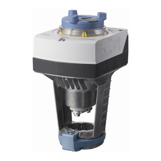
Figure 1:
VA-045PNX024P Electronic Valve Actuator
Product Description
This document describes the hardware installation procedures for the
VA-045PNX024P PICV Actuator, 45lb., Non-Spring Return, 24V,
Proportional 0-10V.
This actuator requires a 24 Vac supply and receives a 0 to 10 Vdc or a 4
to 20 mA control signal to proportionally control a valve. This actuator is
designed to work with 1-1/2- or 2-inch normally open (NO) Pressure
Independent Control Valves with a 5/8-inch (15 mm) stroke.
General Installation Requirements
For proper installation and subsequent operation of each actuator, pay
special attention to the following recommendations:
-
Upon unpacking the product, inspect the contents of the carton for
shipping damages. Do not install damaged actuators.
-
Avoid areas where corroding, deteriorating or explosive vapors,
fumes or gases may be present.
-
Ensure that all equipment is installed according to local, regional,
and national regulations.
Personal injury or loss of life may occur if you do not follow a
procedure as specified.
Equipment damage or loss of data may occur if you do not
follow a procedure as specified.
Take reasonable precautions to prevent electrostatic
discharges to the controller when installing, servicing or
operating the controller. Discharge accumulated static
electricity by touching one's hand to a well-grounded object
before working with the controller.
H a r d w a r e I n s t a l l a t i o n G u i d e
If mounting the actuator to a valve already in line, either
close the shut-off valves in the piping (upstream first, then
downstream) or switch off the pump to allow the differential
pressure in the valve to drop.
Mounting Instructions
Required Tools
-
4 mm hex key, or 10 mm wrench
-
Flat-blade screwdriver or Phillips screwdriver to remove wiring
compartment cover
Estimated Installation Time
-
30 minutes for wiring a factory-installed actuator
-
45 minutes for field replacement of actuator
Advertisement
Table of Contents

Related Manuals for Distech Controls VA-045PNX024P


Summary of Contents for Distech Controls VA-045PNX024P
- Page 1 This document describes the hardware installation procedures for the VA-045PNX024P PICV Actuator, 45lb., Non-Spring Return, 24V, Proportional 0-10V. Mounting Instructions This actuator requires a 24 Vac supply and receives a 0 to 10 Vdc or a 4 to 20 mA control signal to proportionally control a valve.
-
Page 2: Mounting Positions
Weather Shield Components VA-ASK39.1 Weather Shield VA-ASK39.1 protects the actuator when installed outdoors. Provides NEMA 3R protection. Mounting Positions Manual adjuster (with slide switch) Wiring knockouts Position indication Figure 2: Acceptable Indoor Mounting Positions Status indication Housing cover Valve stem coupling Yoke Bonnet connection U-bracket Figure 3: Acceptable Outdoor Mounting Positions with Weather Shield for... -
Page 3: Installation
5. Tighten the U-bracket bolt using a 10 mm wrench (or 4 mm hex key) Installation to 5 Nm (44 in-lbs) torque. See Figure 8. Do not damage or scratch the polished surface of the valve stem. Mounting an Actuator to a Valve 1. - Page 4 Up to 10 actuators can be driven in parallel from a single controller output Select between 0 to 10 Vdc or 4 to 20 mA input signal for terminal Y (0 to with a 1 mA rating. The VA-045PNX024P proportional actuator has an 10 Vdc default).
-
Page 5: Manual Override
Z - Positioning signal forced control being open), then the Function Module (AZX61.1) must be ordered and installed in the VA-045PNX024P with DIP switch 1 set to ON. Parallel Control of Actuators Up to 10 actuators can be driven in parallel from a single controller output Manual Override with a rating of 1 mA. -
Page 6: Function Check And Calibration
Disengaging the setting Calibration When the black slide switch is pushed back in, and the manual adjuster is Calibration is required with modulating actuators, and before the function not pressed down, the manual adjuster returns to Automatic Mode. check. Calibration must be performed manually. Prior to calibrating, ensure that: ... -
Page 7: Troubleshooting
0V corresponds to the valve being closed, and 10V to the valve being open), then the Function Module (VA-AZX61.1) must be ordered and installed in the VA-045PNX024P with DIP switch 1 set to ON. Position Indication The actuator position indicated by the position output signal "U" is calculated by a potentiometer that sends a feedback signal via the U terminal. - Page 8 ©, Distech Controls Inc., 2016. All rights reserved. While all efforts have been made to verify the accuracy of information in this manual, Distech Controls is not responsible for damages or claims arising from the use of this manual. Persons using this manual are assumed to be trained HVAC specialist / installers and are responsible for using the correct wiring procedures and maintaining safe working conditions with fail-safe environments.
- Page 9 ©, Distech Controls Inc., 2015. All rights reserved. While all efforts have been made to verify the accuracy of information in this manual, Distech Controls is not responsible for damages or claims arising from the use of this manual. Persons using this manual are assumed to be trained specialist / installers and are responsible for using the correct wiring procedures and maintaining safe working conditions with fail-safe environments.
Need help?
Do you have a question about the VA-045PNX024P and is the answer not in the manual?
Questions and answers