Advertisement
VA-180GN Series
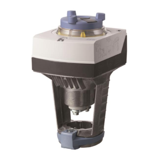
Globe Valve Actuator, 180lb., Non-Spring Return, 24V
Figure 1: VA-180GN Series
Product Description
This document describes the hardware installation procedures for the
following VA-180GN Series globe valve actuators:
VA-180GNX024F
180lb., Non-Spring Return, 24V, Floating
VA-180GNX024P
180lb.,
Proportional 0-10V
General Installation Requirements
For proper installation and subsequent operation of each actuator, pay
special attention to the following recommendations:
-
Upon unpacking the product, inspect the contents of the carton for
shipping damages. Do not install damaged actuators.
-
Avoid areas where corroding, deteriorating or explosive vapors,
fumes or gases may be present.
-
Ensure that all equipment is installed according to local, regional,
and national regulations.
Personal injury or loss of life may occur if you do not follow a
procedure as specified.
Equipment damage or loss of data may occur if you do not
follow a procedure as specified.
Non-Spring
Return,
24V,
H a r d w a r e I n s t a l l a t i o n G u i d e
Take reasonable precautions to prevent electrostatic
discharges to the controller when installing, servicing or
operating the controller. Discharge accumulated static
electricity by touching one's hand to a well-grounded object
before working with the controller.
VA-180GN actuators can only be used for hot or chilled
water, or low pressure (<15 psi) steam installations. Use on
higher temperature systems will damage the actuator and
lead to premature failure.
Mounting Instructions
Required Tools
-
4 mm hex wrench, or 10 mm wrench
-
Flat-blade screwdriver or Phillips screwdriver to remove wiring
compartment cover
Expected Installation Time
-
45 minutes:
Field installation or replacement of actuator
If mounting the actuator to a valve already in line, either
close the shut-off valves in the piping (upstream first, then
downstream) or switch off the pump to allow the differential
pressure in the valve to drop.
Advertisement
Table of Contents

Related Manuals for Distech Controls VA-180GN Series


Summary of Contents for Distech Controls VA-180GN Series
- Page 1 This document describes the hardware installation procedures for the before working with the controller. following VA-180GN Series globe valve actuators: VA-180GNX024F 180lb., Non-Spring Return, 24V, Floating VA-180GN actuators can only be used for hot or chilled VA-180GNX024P 180lb.,...
-
Page 2: Mounting Positions
Mounting Positions Installation Do not damage or scratch the polished surface of the valve stem. Mounting an Actuator to a Valve 1. Ensure stem connection plate in the Valve Stem Coupling is in the OPEN position. See Figure 4. Figure 2. Acceptable Indoor Mounting Positions. Figure 4. - Page 3 Position the actuator to accommodate the wiring. Hold the actuator in place while tightening the actuator U- bracket bolt. 5. Tighten the U-bracket bolt using a 10 mm wrench (or 4 mm Allen wrench) to 5 Nm (44 in-lbs) torque. See Figure 8. Figure 11.
- Page 4 Wiring Flow Characteristic Do not use autotransformers. Use earth ground isolating step-down equal- Class 2 power supply transformers. percentage Determine supply transformer rating by summing total VA of all actuators used. The maximum rating for a Class 2 step-down transformer is 100 VA. It is recommended that no more than 10 actuators are powered by one lin = linear transformer.
- Page 5 Wiring Diagrams for VA-180GNX024F Operation for VA-180GNX024F The actuator accepts a 24 Vac control signal to Y1, which causes the actuator’s stem retainer to move toward the valve (extend). A 24 Vac control signal to Y2 causes the actuator’s stem retainer to move toward the actuator (retract).
-
Page 6: Commissioning And Operation
Manual Override Automatic Mode: When the motor drives the manual adjuster turns. In Automatic Mode, the manual adjuster is used for indication of travel. If the manual adjuster is held firm in this mode, there is no transmission of power to the gear train. - Page 7 Calibration (VA-180GNX024P Only) Table 1. Calibration is required with modulating actuators, and before the function check. Calibration must be performed manually. Prior to calibrating, ensure that: Actuator is properly connected to a valve. Housing cover is removed. Power is applied. If required, calibration can be repeated any number of times.
-
Page 8: Troubleshooting
Table 1. LED Indication and Status. VA-180GNX024P Function Check Remarks, Perform the function check for modulating actuators after calibration Indication Operating state troubleshooting with a point test according to the following table: Automatic mode Normal operation Table 2. Modulating Function Check. Wait until calibration is Calibration finished... - Page 9 Dimensions Weight ► ►► Product Numbers lbs (kg) VA-180GNX024P 9.53 4.88 5.91 2.68 3.23 3.15 3.94 3.94 7.87 VA-180GNX024F (242) (124) (150) (68) (82) (80) (100) (100) (200) (1.85) With VA-ASK39.1 10.51 6.06 11.81 7.87 3.94 – – – – (267) (154) (300)
- Page 10 ©, Distech Controls Inc., 2014. All rights reserved. While all efforts have been made to verify the accuracy of information in this manual, Distech Controls is not responsible for damages or claims arising from the use of this manual. Persons using this manual are assumed to be trained HVAC specialist / installers and are responsible for using the correct wiring procedures and maintaining safe working conditions with fail-safe environments.
Need help?
Do you have a question about the VA-180GN Series and is the answer not in the manual?
Questions and answers