Table of Contents
Advertisement
Quick Links
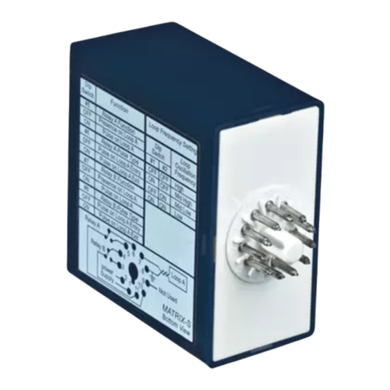
M A T R I X - 3
D I G I T A L
APPLICATIONS
The MATRIX Digital Inductive Loop Detector range is the ideal solution for parking barrier control, motorized gates and
doors, vehicle access control and industrial control systems.
The MATRIX range is a high performance single or dual channel vehicle detector packaged in a compact housing, the
connection is made with an industrial standard 11-pin round connector.
Two versions listed below are available, single or dual channel, and 3 possibilities for the power supply :
TECHNICAL
Technology
Tuning
SPECIFICATIONS
Detection mode
Presence time
Pulse time output
Inductance range
Frequency range
Frequency steps
Sensitivity ( L/L)
Reaction time
Setup time at power on
Power supply
Mains Frequency
Power Consumption
Storage temperature
range
DESCRIPTION
OF
THE SENSOR
(only with dual loop)
LOOPS
A. CABLE SPECIFICATIONS FOR LOOP AND FEEDER
INSTALLATION
TIPS
B. LOOP GEOMETRY
Ea
Eb
75.5524.02 20091008
I N D U C T I V E
MATRIX-3-S12-24 : Single loop detector with 12 to 24 V AC/DC power supply
MATRIX-3-D12-24: Dual loop detector with 12 to 24 V AC/DC power supply
inductive loop
automatic
presence
1 min to in nity (permanent
presence)
100 ms or 500 ms
20 µH to 1000 µH
20 kHz to 130 kHz
4 for single loop
2 for dual loop (for each loop)
0.005% to 0.5%
25 ms for single loop
50 ms for dual loop (each channel)
1.6 s (Matrix-3-S)
2.2 s (Matrix-3-D)
12-24 AC/DC ±10%
48 to 62 Hz
< 2.5 W
–30°C to +70°C
Power LED
Detection state LED
Detection state LED
• 1.5mm
cross section area
2
• Multi-strand cable
• Insulation material : PVC or Silicone
• For the feeder cable, the wire must be twisted at least 15 times by meter
• Feeder for long runs used for foil screened cable is recommended (earth at equipment end only)
• The feeder cable must be rmly xed to avoid any false detection (max length : 100 m)
• Waterproof cable junction box is required
L
Feeder cable
U S E R ' S G U I D E
L O O P
Operating temperature
range
Degree of protection
2 Output relays (free potential change-over
contact)
• max contact voltage : 230 VAC
• max contact current : 5A (resistive)
LED indicators
• 1 green LED : power
• 1 red LED : Loop status 1
• 1 red LED : Loop status 2
Protections
• loop insulation transformer
• zener diodes
• gas discharge clamping
Connection
Dimensions
Weight
Product compliance
Presence time
adjustment
Sensitivity adjustment
potentiometer
(only with dual loop)
Sensitivity adjustment
potentiometer
• With two adjacent loops connected to a dual channel sensor, it is possible for
these loops to share a common slot, if so required.
As the channels are multiplexed, no interference will occur.
• Avoid large loops or long feeder (max 100 m), the sensitivity will be a ected.
S E N S O R S
–30°C to +40°C
IP40
standard 11-pin round
connector 86CP11
77mm (H) x 40mm (W) x 75mm (D)
< 200gr
R&TTE 1999/5/EC
EMC 2004/108/EC
UL listed equipment for UL 508
Main connector
(86CP11)
Page 1 of 4
Advertisement
Table of Contents

Related Manuals for BEA MATRIX-3


Summary of Contents for BEA MATRIX-3
- Page 1 Two versions listed below are available, single or dual channel, and 3 possibilities for the power supply : MATRIX-3-S12-24 : Single loop detector with 12 to 24 V AC/DC power supply MATRIX-3-D12-24: Dual loop detector with 12 to 24 V AC/DC power supply...
- Page 2 • Con guration # 1 : single loop detector (MATRIX-3-S) • Con guration # 2 : dual loop detector in independent mode (MATRIX-3-D with dip switch #10 OFF) • Con guration # 3 : dual loop detector in combined mode (MATRIX-3-D with dip switch #10 ON) B.
- Page 3 Dip Switch #7 Relay B function : presence or pulse or loop selection for relay B pulse : pulse on Loop B or pulse on Loop A (used with dual loop in (only MATRIX-3-D) combined mode) Dip Switch #8 Relay B Pulse type : entry or exit (used only at pulse function)
- Page 4 #10 setting required and adjust dip switch #10 Trade Name: MATRIX Model No: MATRIX-3-S12-24 Do not leave problems unresolved. If a satisfactory solution cannot be achieved after troubleshooting a MATRIX-3-D12-24 problem, please call B.E.A., Inc. If you must wait for the following workday to call B.E.A., leave the door inoperable until satisfactory repairs can be made.
Need help?
Do you have a question about the MATRIX-3 and is the answer not in the manual?
Questions and answers