Table of Contents
Advertisement
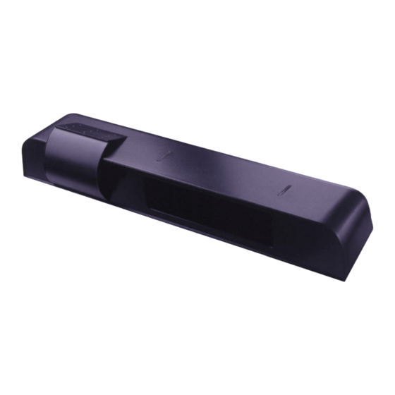
We open up New Horizons
COMBINED
The Wizard SMR (PN:10WIZARDSMR) combines k-band microwave and focused active infrared technology to provide
SAFETY &
superior activation and safety for an automatic sliding door system. For activation, the unit provides digitally processed and
ACTIVATION
sophisticated motion tracking technology for unidirectional sensing when energy conservation is critical. For safety, the unit
SENSOR
emits 2 rows of 24 beams of focused presence technology that provides extraordinary safety. The active infrared remains
active even when the door is closing. Serial numbers 52000 and greater provide the added ability for an "ALL RELAY" output,
making it compatible with older non-microprocessed control boxes.
TECHNICAL
DESCRIPTION
SPECIFICATIONS
Supply voltage
Power frequency
Power consumption
Mounting height
SMR data input
Delay of the output activation after stimulation
3-color LED
Temperature range
Degree of protection
Product conformity
Dimensions
Weight
Housing material
Color of Housing
Cable length
Technology
Detection field (standard)
Detection mode
Angle :
Output specification
Output hold-time
Manual adjustment
Remote control adjustments
75.0127 V3 Jul. 2003 [Rev. 8/13/2004]
USERS GUIDE
COMBINED ACTIVATION & SAFETY SENSOR
• Standard
• High
MOTION SENSOR
Microwave and microprocessor
Transmitter frequency :24.125 GHz
Transmitter radiated power : <20 dBm EIRP
Transmitter power density : < 5 mW/cm²
• Wide field
13'0" W x 6'6" D
• Narrow field
6'6" W x 8'2" D
Minimum detection speed
2 inches / sec. (measured in the sensor axis)
from 15° to 50° in elevation (adjustable)
Relay (free of potential change-over contact) :
• Max contact voltage : 42V AC/DC
• Max contact current : 1A (resistive)
• Max switching power : 30W (DC) / 60VA (AC)
0.5s to 9s (adjustable)
• orientation of sensing field (mechanically)
• shape of the sensing field (choice of antenna)
• multiple functions (using push buttons).
• Sensitivity.
• Hold time.
• Detection mode.
• Immunity
• Output configuration.
WIZARD SMR
SPECIFICATION
12 to 24 VAC / VDC: -5% to +10%
50 / 60 Hz
< 3 W
5'9" to 8'2"
8'2" to 13"
10 to 30 V DC
transistor : < 1ms
• RED :
presence detection
• GREEN : motion detection
• ORANGE :monitoring process
-30° F to +131° F
NEMA 3S / (IP54)
R&TTE 1999/5/EC & EMC 89/336/EEC
BZT Germany, TÜV
10.4 " x 2.2 " x 1.9 "
.55 lbs / 250 g
ABS & LURAN S
Anthracite gray (standard), aluminum or white finish
8' of six-conductor cable
Focused active infrared and
Self-monitored microprocessor
Spot diameter (standard) : 4" max
Number of spots : 24 or 12 spots by
curtain
Number of curtains : 2
6'6" W x 13.75" D
3'3" W x 13.75" D
Response time : < 128ms
from - 4° to + 4° (adjustable)
Transistor (optocoupled transistor)
• Max output current : 100 mA
• Max switching power : 48 V DC
1s (fixed)
• orientation of sensing field
• shape of the sensing field (choice of
front lens)
• multiple functions (by push buttons).
• Sensitivity.
• Auto-learn time
• Monitoring mode
• Number of Curtains
• Relay / Transistor configuration
• Rain Mode
• Snow Mode
Page 1 of 17
Advertisement
Table of Contents

Related Manuals for BEA WIZARD SMR


Summary of Contents for BEA WIZARD SMR
- Page 1 We open up New Horizons COMBINED The Wizard SMR (PN:10WIZARDSMR) combines k-band microwave and focused active infrared technology to provide SAFETY & superior activation and safety for an automatic sliding door system. For activation, the unit provides digitally processed and ACTIVATION sophisticated motion tracking technology for unidirectional sensing when energy conservation is critical.
- Page 2 COMPONENT ID CABLE I.R. REMOTE RECEIVER COVER LED INDICATOR ANTENNA STORAGE MANUAL SET-UP MOUNTING SCREWS BUTTONS MOTION SENSOR PRESENCE SENSOR FRONT LENSES SAFETY • Shut off all power going to the header before attempting any wiring procedures. PRECAUTIONS • Maintain a clean & safe environment when working in public areas. •...
- Page 3 ELECTRICAL With Wizard in place, locate the enclosed cable and feed the stripped end through the wire INSTALLATION passage hole in header from the Wizard side as shown in Picture (F). Leave enough slack to allow connection to the Wizard and proper routing of wire around the plastic posts (E). Please observe proper routing of the cable as shown –...
- Page 4 MECHANICAL ADJUSTMENTS Insert the desired microwave planar antenna for a narrow or wide field of detection. Refer to the diagram below for approximation of field size for each pattern. WIDE NARROW 7’-0” height = [13’ (W) X 6’ 6” (D)] [6 6”...
- Page 5 At the standard mounting height, one complete clockwise turn of the adjustment screw will move the pattern approximately 3 inches closer to the door. The precise location of the infrared beam may be found by using the BEA Spot-finder (PN: 10SPOT) after the Wizard has been powered up.
- Page 6 WIZARD SMR All program changes and inquiries can only be accomplished while the Wizard is unlocked. PROGRAMMING GUIDE – LOCKING & UNLOCKING USER’S ACTIONS DEFAULT LED STATUS UNLOCK Press the UNLOCK key once, then enter 0000 The red LED will flash quickly after your 4-digit code to unlock the Wizard.
- Page 7 SN 52000 and greater. SMR (Self-Monitoring Ready) mode is After pressing the SMR key, the red enabled for the use with BEA’s DCU (Door LED flashes quickly. After pressing a Control Unit). It is disabled for all other number button, the red LED flashes applications.
- Page 8 The only required setting on the Wizard SMR to enable Rain Mode is IR Sensitivity, which must be set to a value of 2 (normal). This mode will automatically expire upon a power reset, or upon expiration of one hour.
- Page 9 MANUAL SET-UP • Set-up of the Wizard may be accomplished by the use of two Wizard mounted programming buttons. (without remote) The procedures below indicate how to program using these buttons. • The two set-buttons are located at the right side of the Wizard (as viewed when mounted to header). To begin, briefly press the right button and move away from the sensing patterns.
- Page 10 MANUAL SET-UP EXAMPLE : Change radar sensitivity from 7 to 9 and set hold time to 4 seconds: (without remote) – Press the right button for 2 settings, you will enter the customizing mode Cont. • The green LED flashes once (parameter 1) •...
- Page 11 Power supply for Wizard: 12 to 24 VAC / VDC: -5% to +10% b. Check SMR setting on each Wizard. The SMR should be disabled unless system is being used with BEA’s Door Control Unit (DCU). c. Check Relay Configuration for each Wizard. Refer to page 6.
- Page 12 Adjust infrared curtain and launch a new set- Wizard will not respond to Improper SMR setting 1. If the Wizard is NOT being used with a BEA motion. DCU, set SMR to a value of 0. See page 8. ACCESSORIES •...
- Page 13 ADDENDUM 1 – The purpose of the addendum is to accommodate for the differences in the Standard Rocker Switch package and WIZARD WITH the Rotary Switch package. The standard wiring provided with the Rotary Switch Package is incompatible when STANLEY using the partial opening switch selection with the Wizard sensor system.
- Page 14 BESAM CUJ-9 AMD II SLIDING DOOR WITH WIZARD SYSTEM INTERIOR WIZARD Reset 0 VDC Part. open Exit * Optional - connect 0 VDC 24 VAC to reset (TB1 R) if required. Stop Impulse Pres. Impulse 1 C-Switch; 0 v Pres. Impulse 2 18 VDC 0 VDC EXTERIOR WIZARD...
- Page 15 BESAM UNISLIDE SLIDING DOOR WITH WIZARD SYSTEM WIZARD INTERIOR UniSlide Control + 24 VDC MONITORED SAFETY/ONLY PHOTOCELL C-SWITCH/MONITORED INNER IMPULSE STOP IMPULSE PRESENCE IMPULSE 2 24 V PRESENCE IMPULSE 1 115 VAC TRANSFORMER - 0 VDC + 24 VDC SYNCHRONIZING OUTPUT SYNCHRONIZING INPUT WIZARD EXTERIOR KEY IMPULSE...
- Page 16 POWER INPUT 120 VAC ACCESSORIES 24 VAC PINS 3,4 3-PIN 96005-900 4 PIN WHITE LOOK-SEE OUTPUT PINS 17,18 GREEN QUANTUM-SLIDE 96010-900 MORNING ENTRY PINS 15,16 BLACK ACCESSORIES 24 VDC PIN 1(+) PIN 2(-) TRANSFORMER BOX WEATHERWISE PINS 11,12 QUANTUM -SLIDE BREAKAWAY PINS 13,14 EXTERIOR ACTIVATE PINS 9,10 CONTROL BOX...
- Page 17 HORTON C2150 CONTROL WITH WIZARD SYSTEM WIZARD INTERIOR C2150 CONTROL +24VDC INTERIOR SW EXTERIOR SW COMMON + 24VDC SAFETY BEAM 24 V COMMON 115 VAC TRANSFORMER TOGGLE SW COMMON CLS MON SW COMMON WIZARD EXTERIOR PARTIAL OPEN 2WAY/ 1 WAY NIGHT SW COMMON DAY/NITE SW...
Need help?
Do you have a question about the WIZARD SMR and is the answer not in the manual?
Questions and answers