Table of Contents
Advertisement
Quick Links
Visit website for
available languages of
this document.
Download the BEA DECODER app
for a quick overview of settings
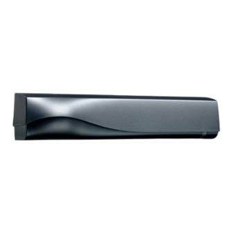
DESCRIPTION
1
3
20.5349
ACCESSORIES
10IMB
Bracket accessory
35.1609: black cover
35.1302: white cover
35.1303: silver cover
This device can be expected to comply with Part 15 of the FCC Rules, provided it is assembled in exact accordance with the instructions
provided with this kit. Operation is subject to the following conditions: (1) this device may not cause harmful interference, and (2) this
device must accept any interference received, including interference that may cause undesired operation.
75.5751.12 IXIO-DT1 20230913
1.
cover
2.
LED window
3.
radar antenna
4.
AIR curtain width adjustment
5.
LCD
Ceiling accessory
Curved door accessory
MOTION AND PRESENCE SENSOR FOR
5
4
6
6.
7.
8.
9.
10ICA
10CDA
IXIO-DT1
AUTOMATIC SLIDING DOORS
2
8
7
AIR lenses
AIR curtain angle adjustment knob
main adjustment knob
main connector
10URA
Universal rain accessory
10IXIOSPACER
Spacer
9
Page 1 of 12
Advertisement
Table of Contents

Related Manuals for BEA IXIO-DT1


Summary of Contents for BEA IXIO-DT1
- Page 1 IXIO-DT1 MOTION AND PRESENCE SENSOR FOR Visit website for AUTOMATIC SLIDING DOORS available languages of this document. Download the BEA DECODER app for a quick overview of settings DESCRIPTION cover AIR lenses LED window AIR curtain angle adjustment knob radar antenna...
-
Page 2: Installation
BEA, Inc. does not guarantee any use of the sensor/device outside of its intended purpose. BEA, Inc. strongly recommends that installation and service technicians be AAADM-certifi ed for pedestrian doors, IDA-certifi ed for doors/ gates, and factory-trained for the type of door/gate system. - Page 3 ISO 13849 PL «c» CAT. 2 (under the condition that the door control system monitors the sensor at least once per door cycle) Specifications are subject to change without prior notice. All values measured in specific conditions. 75.5751.12 IXIO-DT1 20230913 Page 3 of 12...
-
Page 4: Navigating In Menus
Note: When querying FIELD SHAPE, the green LED will blink the number of times that it is set to, and then the green LED will blink either 1 time (narrow shape) or 2 times (wide shape). Page 4 of 12 75.5751.12 IXIO-DT1 20230913... -
Page 5: Mounting And Wiring
* The sensor LED will briefly flash RED during monitoring communication with door control, indicating that external monitoring is functional. Monitoring functionality must be active on the sensor, door control, and monitoring wires must be properly connected to the door control. 75.5751.12 IXIO-DT1 20230913 Page 5 of 12... - Page 6 7.2 ft field size: 9 immunity: 2 13’ x 6’6" (wide) 7.2 ft field size: 9 immunity: 2 6’6" x 8’ (narrow) 1 × 1 grid is approximately 3.28 ft × 3.28 ft. Page 6 of 12 75.5751.12 IXIO-DT1 20230913...
- Page 7 Wide setting has 1:1 ratio. For example, a 6-foot mounting height will project a 6-foot detection width at floor. Always verify the actual detection field width by walk-testing according to ANSI 156.10. Additional adjustments are possible by LCD or remote control (see OVERVIEW OF SETTINGS). 75.5751.12 IXIO-DT1 20230913 Page 7 of 12...
- Page 8 + reference picture either hold the knob for 4 seconds, or use the remote control buttons as specified TEST THE PROPER OPERATION OF THE INSTALLATION BEFORE LEAVING THE PREMISES! LED flashes red-green Page 8 of 12 75.5751.12 IXIO-DT1 20230913...
-
Page 9: Overview Of Settings
RESET LOG delete all saved errors POWERSUPPLY supply voltage at power connector PASSWORD LCD and remote control password (0000= no password) OPERATINGTIME power duration since first startup ADMIN enter code to access admin mode 75.5751.12 IXIO-DT1 20230913 Page 9 of 12... - Page 10 Monitoring functionality must be active on the sensor and door control, and monitoring wires must be properly connected to the door control. Note 4 MTF = uni-directional with motion-tracking feature uni + reentry: BEA recommends only adjusting using the LCD Note 5 REDIRECTION setting (F1 on remote control): R1-MW, R2-IR (F1=0): R1 = MW (i.e.
-
Page 11: Led Signals
Check position of cable and cover. The sensor sees the door. Adjust the AIR angle and launch an assisted setup. The sensor is disturbed by Increase the AIR immunity filter. external conditions. 75.5751.12 IXIO-DT1 20230913 Page 11 of 12... - Page 12 Can’t find your answer? Visit www.beainc.com or scan QR code for Frequently Asked Questions! Tech Support & Customer Service: 1-800-523-2462 General Tech Questions: techservices-us@BEAsensors.com | Tech Docs: www.BEAsensors.com Page 12 of 12 75.5751.12 IXIO-DT1 20230913...
Need help?
Do you have a question about the IXIO-DT1 and is the answer not in the manual?
Questions and answers