Table of Contents
Advertisement
STEP 1
INSTALL
STEP 2
WIRING
STEP 3
POWER-ON
STEP 4
SETUP
STEP 5
IR ANGLE
STEP 6
WALK-TEST
STEP 7
DOCUMENTATION
75.5159.09 20090115
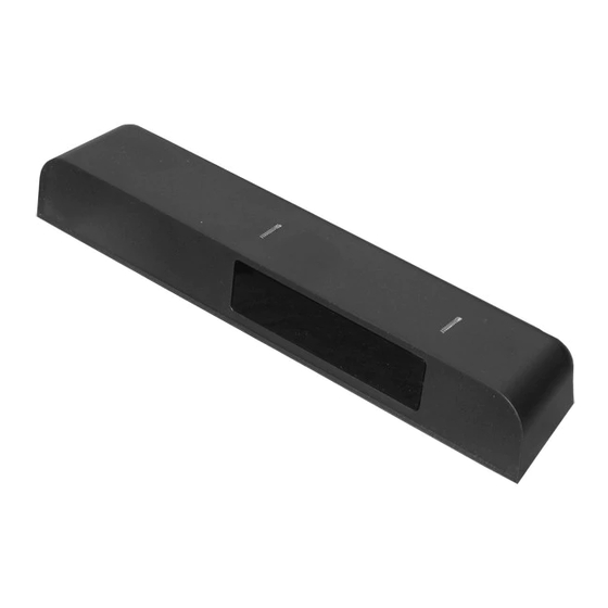
Confirm contents of package: 1 sensor, 1 cable, 1 wide lens (default), 1 narrow lens, mounting template, User's Guide.
Install the sensor at the desired location. Use the enclosed mounting template for drilling locations.
Wire the sensor per the application. Generally, the output wires (brown and blue) will connect to safety at the door
control. The relay output from the IRIS is a dry contact. Note: The IRIS cable is the same as a Wizard II cable. Wire
color and connection points are identified below.
Red
Power: 12 to 24 VAC / DC (+)
Black
Power: 12 to 24 VAC / DC (-)
White
Relay 1: Auxiliary Output
Green
Relay 1: Auxiliary Output
Brown
Relay 2: COM (to COM input at door control)
Blue
Relay 2: NO (to SAFETY input at door control).
Apply the specified power and observe the red LED on the IRIS.
Red LED should come on, and remain on throughout the setup. Door should remain open during setup. When
complete, red LED goes out, and door should close. This takes about 6 seconds if uninterrupted.
IMPORTANT NOTE: During sensor setup, the sensor may or may not cause a door opening cycle. This is because
the output from the sensor may be tied to the safety circuit of the door controller, which is typically disabled at the
closed door position. For a quick setup, this is Ok. For an assisted setup, the installer must launch the setup, then
active the door to the open position immediately thereafter. A normal setup routine will then follow.
The most common defaults have been applied to the sensor. Below, are the most critical for proper door operation,
and are the first ones to check if unexpected behavior occurs:
Relay Configuration: By default it is set to Active (value 4) – the IRIS relay contact closes upon detection. If
passive is required, change the output configuration value to 1. The most obvious indication to this condition is
that the door works in reverse order – no detection results in hold open.
Pulse Frequency: If an interference is suspected from other nearby sensors or IR equipment, change the
frequency of the IRIS. Default is value 1, change to value 3. Values 2 and 4 are not used.
Additionally, the angle of the infrared curtain will need to be adjusted. If the curtain is too close to the door, the door
will appear to recycle on its own. A curtain that is too far from the door will be in violation of applicable standards –
for most applications.
Adjust the curtain so that detection occurs within 3" from the face of the door. Turn the adjustment screw in
clockwise to draw the curtain in closer to the door.
Always walk-test the sensor pattern when completed. The performance of the sensor should comply with all
standards relative to the application.
As a minimum, the sensor pattern width should be equal to or greater than the width of the clear door opening.
To test the performance of the sensor, stand motionless in the detection area for 30 seconds. Door should stay
open with no attempt to close.
Document all work. For future reference, be sure to record the IRIS serial number on your work order.
Educate the Owner / Manager as to the proper operation of the sensor, and door system, and what to do to ensure
safe use of the door in the event of discovering a malfunction. Show them how to perform a daily safety check of the
sensor.
NOTE: Be sure to reference the complete User's Guide if additional information is required.
IRIS \ IRIS-I
QUICK SET-UP GUIDE
1/10
Advertisement
Table of Contents

Related Manuals for BEA IRIS


Summary of Contents for BEA IRIS
- Page 1 Wire the sensor per the application. Generally, the output wires (brown and blue) will connect to safety at the door WIRING control. The relay output from the IRIS is a dry contact. Note: The IRIS cable is the same as a Wizard II cable. Wire color and connection points are identified below.
-
Page 2: Technical Specifications
IRIS / IRIS-I USER GUIDE Description Cover Push-Buttons IR-Presence sensor IR-Prism Main Connector IR curtain adjustment screw Technical Specifications Supply voltage : 12V (– 5%) to 24V (+10%) AC/DC Mains frequency : 50 - 60 Hz Power consumption : < 3 W Mounting height : 6’8”... -
Page 3: Installation
DO NOT attempt any internal repair of the sensor. All repairs and/or component replacements must be performed by BEA, Inc. Unauthorized disassembly or repair…. may jeopardize personal safety and may expose one to the risk of electrical shock ... -
Page 4: Remote Control Setup
IR presence sensing field: select the applicable IR lens – narrow or wide (default) Install the applicable lens into the slots 2 curtains of 12 overlapping spots 2 curtains of 24 overlapping spots at bottom side of sensor. (no holes between spots) (no holes between spots) The default lens is wide. - Page 5 Remote Control adjustments (only when factory settings do not match) Unlock the sensor to enter into adjustment session (if no access code has been Press Unlock key RED LED entered) flashes slowly To change the value of a parameter (ex. Maximum duration of presence Select parameter RED LED Enter new value...
- Page 6 Important Note: Upon detection at the sensor, both relays will be simultaneous triggered. Relay 1 is assigned to the white and green output wires. Relay 2 is assigned to the brown and blue output wires. Both are dry contacts. BEA wiring diagrams show Relay 2 (brown and blue) as the designated output for presence detection.
-
Page 7: Important Programming Notes
The two setup buttons are located at the right side of the IRIS (as viewed when mounted to header). To begin, briefly press the right button and move away from the sensing patterns. -
Page 8: Helpful Hints
VALUE confirmed by RED LED) left button and confirmed by GREEN LED) Not Used Relay hold time Output configuration Auto-learn 0 = IRIS presence sensing 9 = IRIS-I Not Used Not Used IR Immunity Not Used Not Used IR curtain Not Used Height &... - Page 9 PN: 10REMOTE Spotfinder: Used to locate infrared sources. It is helpful in determining location of the infrared curtains emitted by the IRIS. PN: 10SPOT WCA: This is a ceiling adaptor for use on drop ceilings (or otherwise). Maximum ceiling thickness allowed is about ¾”.
-
Page 10: Troubleshooting
Do not leave problems unresolved. If a satisfactory solution cannot be achieved after troubleshooting a problem, please call BEA, Inc. If you must wait for the following workday to call BEA, leave the door inoperable until satisfactory repairs can be made. Never sacrifice the safe operation of the automatic door or gate for an incomplete solution.
Need help?
Do you have a question about the IRIS and is the answer not in the manual?
Questions and answers