Enelion VERTICA Manual
Hide thumbs
Also See for VERTICA:
- Manual (48 pages) ,
- Assembly manual (40 pages) ,
- Installation manual (14 pages)

Subscribe to Our Youtube Channel
Related Manuals for Enelion VERTICA


Summary of Contents for Enelion VERTICA
- Page 1 Enelion VERTICA Manual for Enelion VERTICA Modules, Enelion VERTICA Pole and accessories. Enelion sp. z o.o. support@enelion.com...
- Page 2 Congratulations on the purchase of the Enelion charger and thank you for your trust. Before the installation, make sure that the module packages contain all the elements. Current version of the operation manual can be accessed at: https://enelion.com/en/support/ See the contents of the manual before initiating any activities related to the installation or the activation of the charger.
-
Page 3: Table Of Contents
5. Installation of Enelion VERTICA Pole 5.1. Preparation for installation 5.1.1. Standard connection 5.1.2. Enelion MID Add-on 5.1.3. Enelion Chain Add-on 5.2. Internet connection via Ethernet interface in the LAN 5.2.1. Add-on – Enelion VERTICA Splitter with an additional meter and residual current protection... - Page 4 5.3. Installation of Enelion VERTICA bottom maskingpanels 6. Installation of the Enelion VERTICA Module 6.1. Preparation for installation of the Enelion VERTICA Module with socket 6.2. Preparation for installation of the Enelion VERTICA Module with a cable 6.3. Installation of accessories 6.3.1. Enelion Bridge 6.3.2.
-
Page 5: Important Information
1.1. General Provisions device housing is open. The Enelion charger (here in after referred to as the It is prohibited to use a charger that is mechanically device, charger, or charging terminal) is a charging damaged or indicates a critical error. -
Page 6: Safety Instructions
Vertica - assembly manual 01 - 2024 1.2. Safety instructions Do not carry out external installation during atmo- spheric precipitation or strong winds if there is a risk of water or contaminants entering the device. All actions described in this manual should be per- formed after ensuring that there is no voltage in the power cable. -
Page 7: General Information
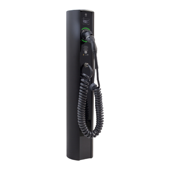
Preparation for use depends on the selected machine functions of the device. Enelion VERTICA Pole is a necessary part of the device. Enelion VERTICA Modules are installed in it, which are the executive part of the charging process. It is available in 2 colors: silver and black. - Page 8 Vertica - assembly manual 01 - 2024 INFO In order to close the Enelion VERTICA Pillar, perform all steps in reverse order. INFO Closing and opening of the Enelion VERTICA Pole does not change depending on the presence of Enelion VERTICA Modules in the device.
-
Page 9: Enelion Vertica Module
2.3.2. Enelion VERTICA module with a ca- 2.3.1. Enelion VERTICA Module with a The Enelion VERTICA module with a cable is a func- socket tional part of the charging station. The Enelion VERTICA module with a socket is a func- tional part of the charging station. -
Page 10: Assembly And Disassembly Of Enelion Vertica Modules
To shut down the device, perform all steps in reverse order. WARRING Enelion VERTICA modules equipped with Enelion VERTICA link are only compatible with Enelion VERTICA poles that are equipped with Enelion VERTICA link modules! Enelion VERTICA modules equipped with Enelion... - Page 11 Vertica - assembly manual 01 - 2024 Open the Enelion VERTICA Pole according to the instructions in section 2.2.1 Opening and closing of the device. Lift the module above the Enelion VERTICA Pole and place the bottom edge in the guide slot. Carefully insert the Enelion VERTICA Module into the power socket until its top edge is flush with the edge of the Enelion VERTICA Pole.
-
Page 12: Design Guidelines For Installation
Vertica - assembly manual 01 - 2024 3. Design guidelines for installation In the TN-C system, you should separate the PEN con- ductor into N and PE, as shown in the diagram below. 3.1. Power network systems for charging stations... -
Page 13: Recommendation For Electrical Connection
Generator lub transformer The entire assembly is mounted on the included TS35 rails at the bottom of the Enelion VERTICA Pillar. Please remember to protect each Enelion VERTICA Module Phase-Phase with a residual current circuit breaker with character- 400 V istics described above. -
Page 14: Equipping With Accessories And Electrical Connections
Equipping with accessories and elec- WARNING trical connections The manufacturer is not responsible for dam- Due to the modular design of the Enelion VERTICA age resulting from non-compliance with the Charging Station, the method of electrical connection above-mentioned recommendations. depends on the accessories used. Additionally, to implement certain device functions, connection with established phase rotation is required. -
Page 15: Connection Type Diagrams
Vertica - assembly manual 01 - 2024 3.4.1. Connection type diagrams Fig. 14: Connection types part 1/2 Design indications of the installation... - Page 16 Vertica - assembly manual 01 - 2024 Fig. 15: Connection types part 2/2. Design indications of the installation...
-
Page 17: Pictorial Diagrams Of Enelion Vertica Modules
Vertica - assembly manual 01 - 2024 3.4.2. Pictorial diagrams of Enelion VERTICA Modules Fig. 16: Pictorial diagrams of Enelion VERTICA Modules part 1/2. Design indications of the installation... - Page 18 Vertica - assembly manual 01 - 2024 Fig. 17: Pictorial diagrams of Enelion VERTICA Modules part 2/2. Design indications of the installation...
-
Page 19: Foundation
An excavation of over 400 mm x 600 mm (diam- eter x depth) or 400 mm x 400 mm x 600 mm Enelion VERTICA Pole can be installed in three ways: (width x length x depth) should be made. Com- pact the soil directly under the foundation to the •... -
Page 20: Appropriate Existing Foundation
In case there is an existing foundation suitable for the purpose, equipped with an electrical connection, meeting the legal and construction requirements, it is possible to install Enelion VERTICA Pole after ensur- ing that Enelion VERTICA Pole is properly attached Fig. 23: Properly constructed foundation with the to the foundation. -
Page 21: Enelion Foundation Set
Enelion VERTICA Pole. To construct the foundation of250 mm x 600 mm (diameter x depth) or 250 correctly, the Enelion foundation set needs to be set mmx 250 mm x 600 mm (width x length x depth). in concrete in the excavation. - Page 22 Vertica - assembly manual 01 - 2024 Fig. 28: Foundation set correctly placed in the excavation Fig. 26: Diagram of placing the foundation set in the excavation Fig. 29: Cross-section of the foundation set cast in the concrete Once the concrete has cured, unscrew the M12 nuts, remove the washers and the upper base plate.
- Page 23 Vertica - assembly manual 01 - 2024 Fig. 32: Screwing nuts and spacer washers onto Fig. 30: Correctly cast foundation set. protruding rods. Fig. 31: Removing of the upper base plate from the foundation set. Secure the bolts partly protruding from the con- crete with bituminous mass (do not cover the thread).
-
Page 24: Installation Of Enelion Vertica Pole
The Enelion VERTICA Pole. accessories should be collected before disposing of the packaging: • Torx Security T25 bit. Enelion VERTICA Pole is mounted to the ground with Open Enelion VERTI- 4 M12 nuts screwed onto the previously prepared CA Pole as instructed in section threaded rods. - Page 25 Vertica - assembly manual 01 - 2024 Fig. 34: Mounting Enelion VERTICA Pole on the foundation. Fig. 36: Mounted and bolted Enelion VERTICA Pole. Fig. 35: Cross-section through the base of the Enelion VERTICA Pole during assembly. Installation of Enelion VERTICA Pole...
-
Page 26: Standard Connection
Enelion VERTICA Pole! HINT The colors of the wires in Enelion VERTICA Pole may not match the colors of the power cables maintaining, however, the guidelines on the Ene- lion VERTICA Module label. - Page 27 Standard connection of Enelion VERTICA Fig. 40: MID meter fitted in Enelion VERTICA Pole. Pole. Mount Enelion MID on the free DIN3 rail and con- In the case of a Enelion VERTICA pole equipped nect the phase conductors and the neutral one with a Enelion VERTICAN module, connect two...
- Page 28 Example of Enelion VERTICA Pole con- The basis for the connection are the markings on nection with the use of MID meter. the packaging label of the Enelion VERTICA mod- ule, intended for this socket of Enelion VERTICA Pole, which should be interpreted in accordance with the attached diagram.
-
Page 29: Enelion Chain Add-On
HINT • In the case of a Enelion VERTICA pole equipped with a Enelion VERTICAN module, attach the In case of two MID meters in the Enelion VERTICA wires in the plug in the screw connector (lift) - Page 30 Fig. 51: Marking place in the pole for Enelion VERTICAN. • For the Enelion VERTICA pole equipped with the Enelion VERTICA link module, termination is done by setting the switch on the Enelion VERTICA link board to the “ON” position.
-
Page 31: Internet Connection Via Ethernet Interface In The Lan
If power is supplied to the charging station using a single cable, it is necessary to use a safe Enelion-pro- vided branching. It includes a connection terminal, Fig. 56: The Enelion Bridge module... - Page 32 The instructions below apply to the situation where the Enelion MID add-on has already been installed. Only copper cables can be used with Enelion VERTICA Splitter terminals. When using the Enelion VERTICA Splitter, follow the presented diagram.
-
Page 33: Installation Of Enelion Vertica Bottom Maskingpanels
5.3. Installation of Enelion VERTICA bottom maskingpanels Enelion VERTICA bottom filler panels cover the lower part of Enelion VERTICA Pole, while providing the ability to read the optional Enelion MID meters. The bottom filler panels should be raised above the Enelion VERTICA Pole, then inserted into the guides and lowered until the panels rest on the springs located at the bottom of Enelion VERTICA Pole. -
Page 34: Installation Of The Enelion Vertica Module
6.2. Preparation for installation of the Ene- lion VERTICA Module with a cable CA Module The Enelion VERTICA module with a cable is delivered individually in a package. INFO Place the packed Enelion VERTICA Module with If you are building an advanced charging station... -
Page 35: Installation Of Accessories
The label on the Enelion VERTICA Module packaging down. In the case of the Enelion VERTICA Module provides key information regarding electrical con- with a cable, the fact of the device having larger nection. -
Page 36: Enelion Rcmb
Opening the Enelion VERTICA Module. Fig. 64: Closing the Enelion VERTICA Module. a stable and flat surface with the front facing down. In the case of the Enelion VERTICA Module with a cable, the fact of the device having larger WARNINIG To get the full range of functions offered by Enelion Bridge, it needs to be configured. „User... -
Page 37: Enelion Moduł Lte
Enelion VERTICA Pole, the Online functions are available Disconnect the 4 wires marked N, L1, L2, L3 from for both Enelion VERTICA Modules. The installation the power connector. Use a PZ2 screwdriver to of Enelion Bridge is identical for the module with a do this. cable and with a socket. INFO To the launch the LTE module, Enelion Bridge Module is required. - Page 38 SMA connector from the outside part of the Ene- lion VERTICA pannel. INFO The antenna should be placed on the dedicated pad to improve a magnetic connection. Connect power cable of the LTE module to a ded- icated socket on the main board. Fig. 73: Properly mounted LTE module. Installation of the Enelion VERTICA Module...
-
Page 39: Activation And Use
After installing add-ons, Enelion VERTICA Modules should be mounted in the installed and connected Enelion VERTICA Pole. Open the Enelion VERTICA Pole (if closed after in- stallation) according to section 2.2.1 Opening and closing of the device. Install the Enelion VERTICA Modules according to section 2.3.3 Assembly and disassembly of Ene-... -
Page 40: Maintenance
Vertica - assembly manual 01 - 2024 7. Maintenance The device is designed to operate in temperatures from -25 C to 55 C. The manufacturer does not guarantee the proper functioning of the charging station in tem- peratures outside the specified range. Chargers that are damaged because of exposure to temperatures below -25 C or above 55 C are not covered under the warranty. -
Page 41: Technical Data
Interface Charging network assembly Enelion Chain Additional elements Meter connector/coupling • Enelion MID Add-ons • Enelion Enelion VERTICA Splitter • RCDB Ambient conditions Working temperature from -25°C to 55°C Storage temperature range from -40°C to 80°C Permitted relative air humidity... -
Page 42: Enelion Vertica Module With A Socket
Vertica - assembly manual 01 - 2024 8.2. Enelion VERTICA Module with a socket Electrical data Supply voltage (Europe) 3 x 230 V / 400 VAC (+-10%) Voltage frequency 50 Hz / 60 Hz TN, TT Network type (IT per request) Overvoltage category III according to EN 60664–1 Rated short-circuit current Effective value < 6 kA according to EN 61439–1... -
Page 43: Enelion Vertica Module With A Cable
Vertica - assembly manual 01 - 2024 8.3. Enelion VERTICA Module with a cable Electrical data Supply voltage (Europe)) 3 x 230 V/400 VAC (+-10%) Voltage frequency 50 Hz/60 Hz TN, TT Network type (IT per request) Overvoltage category III according to EN 60664–1 Rated short-circuit current Effective value < 6 kA according to EN 61439–1... -
Page 44: Technical Description
Vertica - assembly manual 01 - 2024 9. Technical description 9.1. Form with boxes to fill in Charging Station/General Access Charging Station Charging point, an element of public road transport infrastructure Type Enelion VERTICA Pole Model Number ................Module Model Number ................ - Page 45 Vertica - assembly manual 01 - 2024...
- Page 46 Vertica - assembly manual 01 - 2024...
- Page 47 Vertica - assembly manual 01 - 2024...
- Page 48 © 2023 ENELION Pana Tadeusza 50, 80-123 Gdańsk, Poland...
Need help?
Do you have a question about the VERTICA and is the answer not in the manual?
Questions and answers