Enelion Vertica Manual
Hide thumbs
Also See for Vertica:
- Manual (48 pages) ,
- Assembly manual (40 pages) ,
- Installation manual (14 pages)

Subscribe to Our Youtube Channel
Related Manuals for Enelion Vertica


Summary of Contents for Enelion Vertica
- Page 1 Vertica Manual for Vertica Modules, Vertica Pole and accessories. Enelion sp. z o.o. support@enelion.com...
- Page 2 Copyright, Enelion sp. z o.o. The manual may change as the product develops. The information provided may not be correct. All rights reserved. Revision: V 3.9 Number of pages: 40 Released: 05.06.2023...
-
Page 3: Table Of Contents
5.1. Preparation for installation 5.1.1. Standard connection 5.1.2. Enelion MID Add-on 5.1.3. Enelion Chain Add-on 5.2. Internet connection via Ethernet interface in the LAN 5.2.1. Vertica Splitter Add-on with an additional meter and residual current protection 5.3. Installation of Vertica bottom maskingpanels... - Page 4 9. Technical description 9.1. Form with boxes to fill in Congratulations on the purchase of the Enelion charger and thank you for your trust. Before the installation, make sure that the module packages contain all the elements. Current version of the operation manual can be accessed at: https://enelion.com/en/support/...
-
Page 5: Important Information
Vertica - assembly manual 5 - 2023 1. Important information may be plugged in the charger socket. It is forbidden to use any extensions of the charging 1.1. General Provisions cable. Installation and servicing of the device must be per-... -
Page 6: General Information
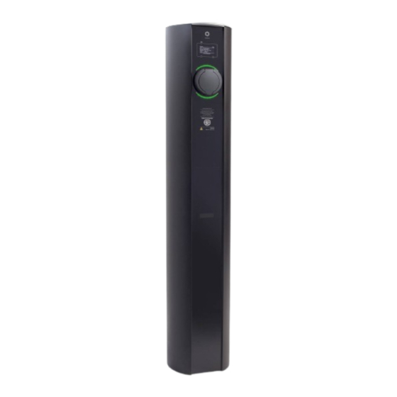
Preparation for use depends on the selected machine functions of the device. Vertica Pole is a necessary part of the device. Vertica Modules are installed in it, which are the executive part of the charging process. It is available in 2 colors: silver and black. - Page 7 Vertica - assembly manual 5 - 2023 INFO In order to close the Vertica Pillar, perform all steps in reverse order. INFO Closing and opening of the Vertica Pole does not change depending on the presence of Vertica Modules in the device.
-
Page 8: Vertica Module
32A three phase vehicles with up to 32A three phase and can be moun- and can be mounted on either side of the Vertica Pole. ted on either side of the Vertica Pole. It is equip-... -
Page 9: Assembly And Disassembly Of Vertica Modules
Open the Vertica Pole according to the instruc- tions in section 2.2.1 Opening and closing of the device. Lift the module above the Vertica Pole and pla- ce the bottom edge in the guide slot. Carefully insert the Vertica Module into the power socket until its top edge is flush with the edge of the Ver- tica Pole. -
Page 10: Design Indications Of The Installation
Due to the modular structure of the Vertica System aker with B or C characteristics and rated current of charging stations, the method of electrical connection 32 A or less, depending on the configuration of the depends on the applied add-ons.Moreover, in order for... - Page 11 Vertica - assembly manual 5 - 2023 vention measures and accident prevention must be taken into account, and escape routes at the installation site must be provided. It is forbidden to install the device in a location where falling objects may damage the charger.
-
Page 12: Connection Type Diagrams
Vertica - assembly manual 5 - 2023 3.3.1. Connection type diagrams Fig. 10: Connection types part 1/2 Design indications of the installation... - Page 13 Vertica - assembly manual 5 - 2023 Fig. 11: Connection types part 2/2. Design indications of the installation...
-
Page 14: Pictorial Diagrams Of Vertica Modules
Vertica - assembly manual 5 - 2023 3.3.2. Pictorial diagrams of Vertica Modules Fig. 12: Pictorial diagrams of Vertica Modules part 1/2. Design indications of the installation... - Page 15 Vertica - assembly manual 5 - 2023 Fig. 13: Pictorial diagrams of Vertica Modules part 2/2. Design indications of the installation...
-
Page 16: Foundation
An excavation of over 400 mm x 600 mm (dia- meter x depth) or 400 mm x 400 mm x 600 mm Vertica Pole can be installed in three ways: (width x length x depth) should be made. Com- pact the soil directly under the foundation to the •... -
Page 17: Appropriate Existing Foundation
In case there is an existing foundation suitable for the purpose, equipped with an electrical connection, meeting the legal and construction requirements, it is possible to install Vertica Pole after ensuring that Vertica Pole is properly attached to the foundation. Fig. 19: Properly constructed foundation with the It is recommended to apply M12 threaded rods. -
Page 18: Enelion Foundation Set
Make a trench in the substrate with dimensions Vertica Pole. To construct the foundation correctly, of250 mm x 600 mm (diameter x depth) or 250 the Enelion foundation set needs to be set in concrete mmx 250 mm x 600 mm (width x length x depth). in the excavation. - Page 19 Vertica - assembly manual 5 - 2023 Fig. 24: Foundation set correctly placed in the excavation Fig. 22: Diagram of placing the foundation set in the excavation Fig. 25: Cross-section of the foundation set cast in the concrete Once the concrete has cured, unscrew the M12 nuts, remove the washers and the upper base plate. The washers and nuts will be needed later...
- Page 20 Vertica - assembly manual 5 - 2023 Fig. 28: Screwing nuts and spacer washers onto Fig. 26: Correctly cast foundation set. protruding rods. Fig. 27: Removing of the upper base plate from the foundation set. Secure the bolts partly protruding from the con- crete with bituminous mass (do not cover the thread).
-
Page 21: Installation Of Vertica Pole
• Torx Security T25 bit. Open Vertica Pole as instructed in section Vertica Pole is mounted to the ground with 4 M12 nuts 2.2.1 Opening and closing of the device screwed onto the previously prepared threaded rods. We recommend the installation on a previously leveled The lower masking panels should be slid up on surface. - Page 22 Vertica - assembly manual 5 - 2023 Fig. 30: Mounting Vertica Pole on the foundation. Fig. 32: Mounted and bolted Vertica Pole. Fig. 31: Cross-section through the base of the Vertica Pole during assembly. Installation of Vertica Pole...
-
Page 23: Standard Connection
A similar connection may be made on the opposi- te side of Vertica Pole. The connection may be performed based on the mar- kings on the packaging label of the Vertica Module intended for this Vertica Pole socket. An example marking specifying the connection of phases in the default order (L3, L2, L1, N) on the label is shown below. - Page 24 Standard connection of Vertica Pole. Fig. 36: MID meter fitted in Vertica Pole. Mount Enelion MID on the free DIN3 rail and con- Connect the two signal wires to the socket located nect the phase conductors and the neutral one to on the PCB board mounted in Vertica Pole. The the meter terminals, in accordance with the mar- red wire to the “A +”...
- Page 25 Fig. 39: Example of Vertica Pole connection with the the packaging label of the Vertica module, inten- use of MID meter. ded for this socket of Vertica Pole, which should be interpreted in accordance with the attached diagram. Fig. 40: MID meter connection diagram.
-
Page 26: Enelion Chain Add-On
HINT conductor wires together, as in the figure be- In case of two MID meters in the Vertica pole, the • For devices on the network segment, prepa- second one should be connected correspondingly, re the communication cables introduced into to the other two pins. -
Page 27: Internet Connection Via Ethernet Interface In The Lan
5.2. Internet connection via Ethernet in- terface in the LAN To ensure internet connection to a charger equip- Connect the above mentioned Ethernet cable to ped with an Enelion Bridge module via the Ethernet the WAN/INTERNET Enelion Bridge module mar- interface: ked with number 2.. Insert the Ethernet patchcord into the device through the gland for communication cables. -
Page 28: Vertica Splitter Add-On With An Additional Meter And Residual Current Protection
Vertica - assembly manual 5 - 2023 overcurrent protection, and residual current protection. The instructions below apply to the situation where the Enelion MID add-on has already been installed. Only copper cables can be used with Vertica Splitter terminals. When using the Vertica Splitter, follow the presented diagram. Fig. 49: Cable routed to the Ethernet socket. -
Page 29: Installation Of Vertica Bottom Maskingpanels
5.3. Installation of Vertica bottom masking- panels Vertica bottom filler panels cover the lower part of Vertica Pole, while providing the ability to read the optional Enelion MID meters. The bottom filler panels should be raised above the Vertica Pole, then inserted into the guides and lowe- red until the panels rest on the springs located at the bottom of Vertica Pole. -
Page 30: Installation Of The Vertica Module
If you are building an advanced charging station system using the Enelion Chain and Enelion Brid- Place the packed Vertica Module with the cable in ge systems, please contact the Enelion support a horizontal position as indicated on the packa- department. -
Page 31: Installation Of Accessories
Place the equipped Vertica Module on a stable and flat surface with t he front facing down. In the case of the Vertica Module with a cable, the fact of the device having larger dimensions sho- uld be taken into account during its installation. -
Page 32: Enelion Rcmb
Place the equipped Vertica Module on a stable and flat surface with the front facing down. In the case of the Vertica Module with a cable, the fact of the device having larger dimensions sho- uld be taken into account during its installation. -
Page 33: Enelion Moduł Lte
6.3.3. Enelion Moduł LTE Enelion LTE module is mounted in the same module as Enelion Bridge. As with the Bridge module, thanks Plug the sensor connector in the socket on the to the integrated Enelion Chain connection within charging controller labeled “P19 P20” placed on the Vertica Pole, the Online functions are available its left side. - Page 34 SMA connector from the outside part of the Ver- tica pannel. INFO The antenna should be placed on the dedicated pad to improve a magnetic connection. Connect power cable of the LTE module to a dedi- cated socket on the main board. Fig. 65: Properly mounted LTE module. Installation of the Vertica Module...
-
Page 35: Activation And Use
Ethernet, make the connection before instal- ling the next Vertica Module. Close the Vertica Pole. Power up the Vertica charging station. I nitialize the Vertica Modules, if not configured, with the provided configuration cards. HINT Full information on the initialization and use of the device can be found in the “User Manual”. -
Page 36: Maintenance
Vertica - assembly manual 5 - 2023 7. Maintenance The device is designed to operate in temperatures from -25 C to 55 C. The manufacturer does not guarantee the proper functioning of the charging station in tem- peratures outside the specified range. Chargers that are damaged because of exposure to temperatures below -25 C or above 55 C are not covered under the warranty. -
Page 37: Technical Data
Vertica - assembly manual 5 - 2023 8. Technical data 8.1. Vertica Pole Electrical data Routing of the power cord Sub-surface Recommended minimum cross-section Power cord cross-section • 5 x 6,0 mm2 (32 A nominal current) Supply voltage (Europe) 3 x 230 V/400 VAC (+-10%) -
Page 38: Vertica Module With A Socket
Vertica - assembly manual 5 - 2023 8.2. Vertica Module with a socket Electrical data Supply voltage (Europe) 3 x 230 V / 400 VAC (+-10%) Voltage frequency 50 Hz / 60 Hz TN, TT Network type (IT per request) Overvoltage category III according to EN 60664–1 Rated short-circuit current Effective value < 6 kA according to EN 61439–1... -
Page 39: Vertica Module With A Cable
Vertica - assembly manual 5 - 2023 8.3. Vertica Module with a cable Electrical data Supply voltage (Europe)) 3 x 230 V/400 VAC (+-10%) Voltage frequency 50 Hz/60 Hz TN, TT Network type (IT per request) Overvoltage category III according to EN 60664–1 Rated short-circuit current Effective value < 6 kA according to EN 61439–1... -
Page 40: Technical Description
Vertica - assembly manual 5 - 2023 9. Technical description 9.1. Form with boxes to fill in Charging Station/General Access Charging Station Charging point, an element of public road transport infrastructure Type Vertica Pole Model Number ................Module Model Number ................ - Page 42 © 2023 ENELION Pana Tadeusza 50, 80-123 Gdańsk, Poland...
Need help?
Do you have a question about the Vertica and is the answer not in the manual?
Questions and answers