Enelion Stilo Assembly Manual
Hide thumbs
Also See for Stilo:
- Getting started (2 pages) ,
- Full manual (18 pages) ,
- Quick manual (2 pages)
Table of Contents
Advertisement
Quick Links
Advertisement
Table of Contents

Subscribe to Our Youtube Channel
Related Manuals for Enelion Stilo


Summary of Contents for Enelion Stilo
- Page 1 Stilo Assembly manual Enelion Sp. z o.o. info@enelion.com...
- Page 2 Copyright, Enelion Sp. z o. o. The manual may change as the product develops. The information provided may not be correct. All rights reserved. Revision: V 3.3 Number of pages: 21 Released: March 8, 2021...
-
Page 3: Table Of Contents
2.1 Opening and closing of Enelion Stilo........ - Page 4 Before the installation, make sure that the module packages contain all the elements. Current version of the operation manual can be accessed at http://enelion.com/en/help/. See the contents of the manual before initiating any activities related to the installation or the activation of the charger.
-
Page 5: Important Information
Stilo - Assembly manual 3 - 2021 1. Important information 1.1. General Provisions It is forbidden to use any extensions of the charging ca- ble. Installation and servicing of the device must be per- The manufacturer is not responsible for loss of health formed by qualified and authorized persons, and re-... -
Page 6: General Information
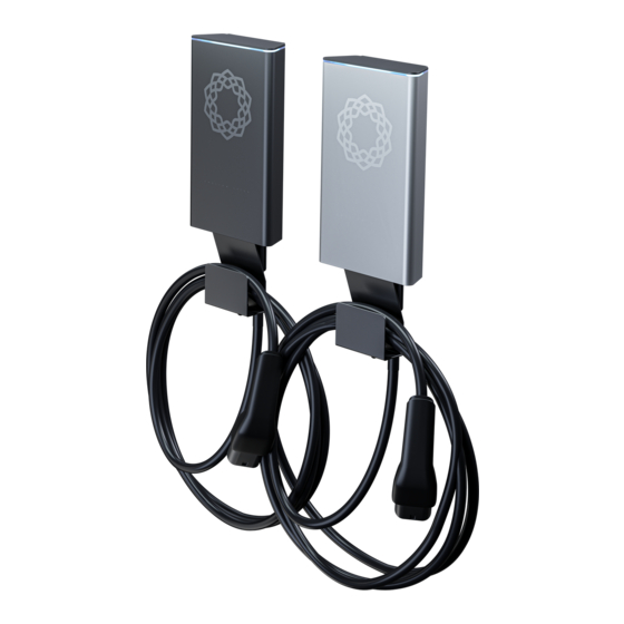
Enelion Bridge, Enelion RCM B protection. Some parameters and functions can be changed by reprogramming the device with the use of the attached RFID card. Enelion Stilo is available in two colors: black and silver. 2.1. - Page 7 Stilo - Assembly manual 3 - 2021 Fig. 2: Location of Enelion Stilo closing bolt. 2. Hold the casing and slide it up the guiding grooves to remove it. Fig. 4: Fully open Enelion Stilo. WARNING Be careful not to crimple the signal tape while fitting the front panel.
-
Page 8: Design Recommendations For The Installation
110 cm of the cable supplying power to (RCD A 30 mA/40 A) in the switchboard with the the left socket is recommended. application of Enelion RCM B – type B Residual Current Monitor, attached to the charging termi- nal. -
Page 9: Location Selection Criteria
3. 100 cm clearance below the bottom edge of the device. Enelion devices equipped with the Enelion Bridge mod- ule can use the Internet connection via the Ethernet in- terface in the LAN network. In order to utilize this func-... -
Page 10: Assembly
• RFID configuration card. 6. Separate the wall anchor from the device by dis- tancing both parts from each other. 3. Open Enelion Stilo in accordance with the in- struction included in section 2.1 Opening and closing of Enelion Stilo. -
Page 11: Cable Routes
12 mm. The detailed connection instructions can be found be- low in 5 Connection. Fig. 9: Enelion Stilo with the wall anchor. Follow the information listed below to choose the appro- priate method of assembly, depending on the mounting surface: 1. - Page 12 5. Put the open (according to section 2.1 Opening and closing of Enelion Stilo) device to its final po- sition by threading the power cord through the gland and hook it on the previously installed an- chor.
-
Page 13: Connection
Stilo - Assembly manual 3 - 2021 5. Connection 5.1. Power connection Variant 2 Diagrams of connection types. Charging module Variant 1 Charging module METER fuse METER Electrical switchboard fuse Fig. 12: Connection type diagrams 2./2. Electrical switchboard Fig. 11: Connection type diagrams 1./2. -
Page 14: Standard Power Connection
Connector Connector Type 2 Type 2 Terminal Terminal Fig. 13: Pictorial diagrams of Stilo Modules 5.1.1. Standard power connection 1. Prepare the power supply cable. Remove 250 mm of the main insulation off the power supply cable. Terminate the individual Fig. -
Page 15: Connection Of Communication Wires
Stilo - Assembly manual 3 - 2021 sleeve). HINT The colors of the phase wires in Enelion Box may not match the colors of the power cables, maintaining, however, the guidelines on Enelion Wallbox label. This is a correct and expected situation when using the phase sequence func- tion. -
Page 16: Internet Connections Via Ethernet Interface In Lan Network
4. Use termination for devices at the beginning and To provide the Internet connection to a charger end of the network. Termination is done by equipped with Enelion Bridge module via Ethernet in- placing a jumper on two pins inside the charger terface: marked as TERM. - Page 17 Stilo - Assembly manual 3 - 2021 Fig. 24: Termination of the Ethernet cable accord- ing to TIA-568A/B to 100BaseT. 3. Connect Ethernet cable WAN/INTERNET socket of Enelion Bridge mod- ule marked with number 2. Fig. 25: Enelion Bridge module diagram. Connection...
-
Page 18: Maintenance
Stilo - Assembly manual 3 - 2021 6. Maintenance The device is designed to operate in temperatures from −25 °C to 55 °C. The manufacturer does not guarantee the proper functioning of the charging station in temper- atures outside the specified range. Chargers that are damaged because of exposure to temperatures below −25 °C or above 55 °C are not covered under the war-... -
Page 19: Technical Data
Stilo - Assembly manual 3 - 2021 7. Technical data 7.1. Enelion Stilo Electrical data Routing of the power cord Surface mounted Recommended minimum cross-section Power cord cross-section • 5 x 6,0 mm (32 A nominal current) Supply voltage (Europe) - Page 20 Stilo - Assembly manual 3 - 2021 Ambient conditions Working temperature from −25 °C to 55 °C Storage temperature range from −40 °C to 80 °C Permitted relative air humidity from 5% to 95% Elevation above the sea level max. 2000 m...
- Page 22 © 2021 ENELION Pana Tadeusza 50, 80-123 Gda ´ nsk, Polska...
Need help?
Do you have a question about the Stilo and is the answer not in the manual?
Questions and answers