Advertisement
Quick Links
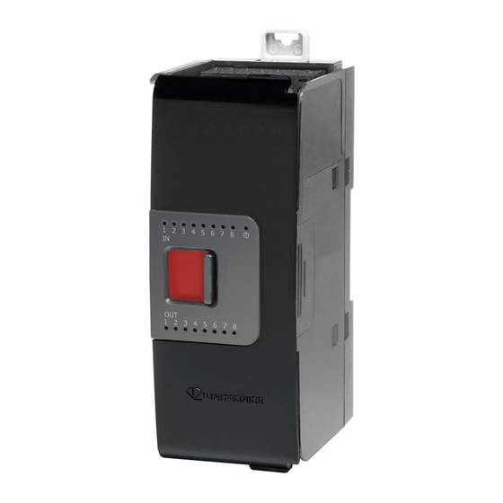
Uni-I/O™ Modules
Uni-I/O™ is a family of Input/Output modules that are compatible with the UniStream™ control
platform.
This guide provides basic installation information for the UIS-04PTN and UIS-04PTKN module.
Technical specifications may be downloaded from the Unitronics website.
The UniStream™ platform comprises
CPU controllers, HMI panels, and local
I/O modules
that snap together to form an
all-in-one Programmable Logic
Controller (PLC).
Install Uni-I/O™ modules:
▪ Onto the back of any UniStream™ HMI
Panel comprising a CPU-for-Panel.
▪ Onto a DIN-rail, using a
Local Expansion Kit.
The maximum number of Uni-I/O™ modules that can be connected to a single CPU controller is limited.
For details, please refer to the specification sheets of the UniStream™ CPU or any of the relevant Local
Expansion Kits.
Before You Begin
Before installing the device, the installer must:
▪ Read and understand this document.
▪ Verify the Kit Contents.
Installation option requirements
If you are installing a Uni-I/O™ module onto:
▪ A UniStream™ HMI Panel; the Panel must comprise a CPU-for-Panel, installed according to the CPU-for-
Panel installation guide.
▪ A DIN-rail; you must use a Local Expansion Kit, available by separate order, to integrate the Uni-
I/O™ modules on the DIN-rail into a UniStream™ control system.
Alert Symbols and General Restrictions
When any of the following symbols appear, read the associated information carefully.
Symbol
Meaning
Danger
Warning
Caution
Caution
▪ All examples and diagrams are intended to aid understanding, and do not guarantee operation.
Unitronics accepts no responsibility for actual use of this product based on these examples.
▪ Please dispose of this product according to local and national standards and regulations.
▪ This product should be installed only by qualified personnel.
▪ Failure to comply with appropriate safety guidelines can cause
severe injury or property damage.
▪ Do not attempt to use this device with parameters that exceed
permissible levels.
▪ Do not connect/disconnect the device when power is on.
Unitronics
Description
The identified danger causes physical and property damage.
The identified danger could cause physical and property damage.
Use caution.
User Guide
UIS-04PTN, UIS-04PTKN
1
Advertisement

Related Manuals for Unitronics UIS-04PTN


Summary of Contents for Unitronics UIS-04PTN
- Page 1 ▪ All examples and diagrams are intended to aid understanding, and do not guarantee operation. Unitronics accepts no responsibility for actual use of this product based on these examples. ▪ Please dispose of this product according to local and national standards and regulations.
- Page 2 Tricolor LED, Green/Red/Orange ▪ Refer to the module's specification sheet for LED indications. Module door Shipped covered with protective tape to prevent the door from being scratched. Remove tape during installation. Screw holes Enable panel-mounting; hole diameter: 4mm (0.15”). Unitronics...
- Page 3 UIS-04PTN, UIS-04PTKN User Guide About the I/O Bus Connectors The I/O Bus connectors provide the physical and electrical connection points between modules. The connector is shipped covered by a protective cover, protecting the connector from debris, damage, and ESD. The I/O Bus - Left (#3 in diagram) can be connected to either a CPU-for-Panel, a Uni-COM™...
- Page 4 You can number modules for reference purposes. A set of 20 stickers is provided with every CPU-for-Panel; use these stickers to number the modules. ▪ The set contains numbered and blank stickers as shown in the figure to the left. ▪ Place them on the modules as shown in the figure to the right. Unitronics...
- Page 5 Class I, Division 2, Groups A, B, C et D. Cette note fait référence à tous les produits Unitronics portant le symbole UL - produits qui ont été certifiés pour une utilisation dans des endroits dangereux, Classe I, Division 2, Groupes A, B, C et D.
- Page 6 All wiring diagrams and instructions in this document refer to the Uni-I/O™ connection points. These points are arranged in two groups of 2 points as shown in the figure to the right. Top group Input connection points (0-1) Bottom group Input connection points (2-3) Unitronics...
- Page 7 Ensure shield continuity when extending shielded cables. ➢ For detailed information, refer to the document System Wiring Guidelines, located in the Technical Library in the Unitronics’ website. Wiring the RTD Inputs ▪ The inputs are not isolated. ▪ When connecting 3- or 4-wire RTDs, make sure to use conductors of the same type, width, and length for all RTD wires, otherwise module accuracy will degrade.
- Page 8 UniStream™ Technical Specifications UniStream® Uni-I/O™ Modules UIS-04PTN, UIS-04PTKN This guide provides specifications for Unitronics’ Uni-I/O™ modules UIS-04PTN and UIS-04PTKN. Those modules comprise: • 4 RTD inputs Uni-I/O modules are compatible with UniStream® family of Programmable Logic Controllers. They may be either snapped onto the back of a UniStream® HMI Panel next to a CPU-for-Panel to create an all-in-one HMI + PLC controller, or installed on a standard DIN Rail using a Local Expansion Adapter.
- Page 9 UIS-04PTN, UIS-04PTKN User Guide UIS-04PTKN input range Input Type Nominal Values Over/Under-range Values * PT1000 -200°C ≤ T ≤ 850°C Under-range: 0.00385 (-328°F ≤ T ≤ 1,562°F) -220°C ≤ T < -200°C 0.00392 (-364°F ≤ T < -328°F) Over-range: 850°C < T ≤ 860°C (1,562°F <...
- Page 10 -30°C to 70°C (-22°F to 158°F) Relative Humidity 5% to 95% (non-condensing) (RH) Operating altitude 2,000 m (6,562 ft) Shock IEC 60068-2-27, 15G, 11ms duration Vibration IEC 60068-2-6, 5Hz to 8.4Hz, 3.5mm constant amplitude, 8.4Hz to 150Hz, 1G acceleration Unitronics...
- Page 11 UIS-04PTN, UIS-04PTKN User Guide Dimensions Weight 100 g (0.220 lb) Size Refer to the images below Bottom View Side View Front View Unitronics...
- Page 12 The tradenames, trademarks, logos and service marks presented in this document, including their design, are the property of Unitronics (1989) (R"G) Ltd. or other third parties and you are not permitted to use them without the prior written consent of Unitronics or such third party as may own them.
Need help?
Do you have a question about the UIS-04PTN and is the answer not in the manual?
Questions and answers