Advertisement
Quick Links
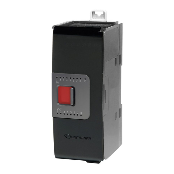
Uni-I/O™ Modules
Uni-I/O™ is a family of Input/Output modules that are compatible with the UniStream™ control platform.
This guide provides basic installation information for UID-0808R, UID-0808T, UID-0808THS, UID-1600,
UID-0016R, and UID-0016T modules.
Technical specifications may be downloaded from the Unitronics website.
The UniStream™ platform comprises
CPU controllers, HMI panels, and local
I/O modules
that snap together to form an
all-in-one Programmable Logic
Controller (PLC).
Install Uni-I/O™ modules:
▪ Onto the back of any UniStream™ HMI
Panel comprising a CPU-for-Panel.
Onto a DIN-rail, using a
▪
Local Expansion Kit.
The maximum number of Uni-I/O™ modules that can be connected to a single CPU controller is limited.
For details, please refer to the specification sheets of the UniStream™ CPU or any of the relevant Local
Expansion Kits.
Before You Begin
Before installing the device, the installer must:
▪ Read and understand this document.
▪ Verify the Kit Contents.
Installation option requirements
If you are installing a Uni-I/O™ module onto:
▪ A UniStream™ HMI Panel; the Panel must comprise a CPU-for-Panel, installed according to the CPU-for-
Panel installation guide.
A DIN-rail; you must use a Local Expansion Kit, available by separate order, to integrate the Uni-I/O™
▪
modules on the DIN-rail into a UniStream™ control system.
Alert Symbols and General Restrictions
When any of the following symbols appear, read the associated information carefully.
Symbol
Meaning
Danger
Warning
Caution
Caution
▪ All examples and diagrams are intended to aid understanding, and do not guarantee operation. Unitronics
accepts no responsibility for actual use of this product based on these examples.
▪ Please dispose of this product according to local and national standards and regulations.
▪ This product should be installed only by qualified personnel.
▪ Failure to comply with appropriate safety guidelines can cause severe injury or property damage.
▪ Do not attempt to use this device with parameters that exceed permissible levels.
▪ Do not connect/disconnect the device when power is on.
Unitronics
User Guide
UID-0808R, UID-0808T, UID-0808THS
UID-1600, UID-0016R, UID-0016T
The identified danger causes physical and property damage.
The identified danger could cause physical and property damage.
Description
Use caution.
1
Advertisement

Related Manuals for Unitronics UID-0808R


Summary of Contents for Unitronics UID-0808R
- Page 1 Caution Use caution. ▪ All examples and diagrams are intended to aid understanding, and do not guarantee operation. Unitronics accepts no responsibility for actual use of this product based on these examples. ▪ Please dispose of this product according to local and national standards and regulations.
- Page 2 Tricolor LED, Green/Red/Orange ▪ Refer to the module's specification sheet for LED indications. Module door Shipped covered with protective tape to prevent the door from being scratched. Remove tape during installation. Screw holes Enable panel-mounting; hole diameter: 4mm (0.15”). Unitronics...
- Page 3 UID-0808R, UID-0016R, UID-0808T, UID-0016T, UID-1600 User Guide About the I/O Bus Connectors The I/O Bus connectors provide the physical and electrical connection points between modules. The connector is shipped covered by a protective cover, protecting the connector from debris, damage, and ESD.
- Page 4 Class I, Division 2, Groups A, B, C et D. Cette note fait référence à tous les produits Unitronics portant le symbole UL - produits qui ont été certifiés pour une utilisation dans des endroits dangereux, Classe I, Division 2, Groupes A, B, C et D.
- Page 5 UID-0808R, UID-0016R, UID-0808T, UID-0016T, UID-1600 User Guide Cet équipement est adapté pour une utilisation en Classe I, Division 2, Groupes A, B, C Attention ▪ D, ou dans Non-dangereux endroits seulement. ▪ Le câblage des entrées/sorties doit être en accord avec les méthodes de câblage selon la Classe I, Division 2 et en accord avec l’autorité...
- Page 6 UniStream™ UID-0808R UID-0808T UID-0016R UID-0016T UID-1600 UID-0808THS Unitronics...
- Page 7 Connect the power supply 0V to the earth of the system. ▪ For detailed information, refer to the document System Wiring Guidelines, located in the Technical Library in the Unitronics’ website. Wiring the Inputs: UID-0808R, UID-0808T, UID-1600 UID-0808R The inputs are arranged in two isolated groups: UID-0808T ▪...
- Page 8 ▪ Use sink input wiring to connect a sourcing (pnp) device. ▪ Use source input wiring to connect a sinking (npn) device. Wiring Relay Outputs: UID-0808R, UID-0016R Output's power supply The relay outputs require an external 24VDC power supply. Connect the 24V and 0V terminals as shown in the figure below.
- Page 9 UID-0808R, UID-0016R, UID-0808T, UID-0016T, UID-1600 User Guide UID-0808R The outputs are arranged in two isolated groups: ▪ O0-O3 share common CM2 ▪ O4-O7 share common CM3 UID-0016R The outputs are arranged in four isolated groups: ▪ O0-O3 share common CM0 ▪...
- Page 10 Use shielded cable for wiring O0 or O1 when they are set to operate as High Speed PWM outputs. Caution ▪ If Outputs O0 and O1 are to function as high- speed outputs, connect them using CM2. Do not connect CM2 to the system 0V. Unitronics...
- Page 11 UniStream™ HMI Panel next to a CPU-for-Panel to create an all-in-one HMI + PLC controller, or installed on a standard DIN Rail using a Local Expansion Kit. Installation Guides are available in the Unitronics Technical Library at www.unitronicsPLC.com. This specification sheet refers to the models in the following table:...
- Page 12 Pulse/Dir Mode figure below) Pulse width Quadrature mode: 0.8s min. for each state in Quadrature Mode figure below). Pulse/Direction mode: 1.5s min. for each state in Pulse/Dir Mode figure below). Cable Shielded twisted pair Quadrature Mode Pulse/Direction mode Unitronics...
- Page 13 UID-0808R, UID-0016R, UID-0808T, UID-0016T, UID-1600 User Guide Outputs UID-0808R UID-0016R UID-0808T UID-0016T Number of outputs Output type Relay, SPST-NO (Form A) Transistor, Source Isolation groups Two groups of Four groups of One group One group 4 outputs each 4 outputs each...
- Page 14 3kHz max. (Load resistance < 4kΩ) Cable (PWM mode) O0, O1: Shielded twisted pair O4, O5: Shielded or unshielded Outputs Power Supply UID-0808THS Nominal operating voltage 24VDC Operating voltage 20.4 – 28.8VDC Maximum current 30mA@24VDC consumption IO/COM Bus UID-0808THS Bus current consumption 120mA max. Unitronics...
- Page 15 UID-0808R, UID-0016R, UID-0808T, UID-0016T, UID-1600 User Guide LED Indications Input LEDs Green Input state Output LEDs Green Output state Status LED A triple color LED. Indications are as follows: Color LED State Status Operating normally Green Slow blink Boot Rapid blink...
- Page 16 UniStream™ Dimensions UID-0808R UID-0016R UID-0808T UID-0808THS UID-0016T UID-1600 Weight 0.15 Kg 0.17 Kg 0.13 Kg 0.13 K 0.13 Kg 0.13 Kg (0.331 lb) (0.374 lb) (0.287 lb) (0.287 lb) (0.287 lb) (0.287 lb) Size Identical for all models, as shown in the images below...
- Page 17 6. Current consumption does not include load current. The information in this document reflects products at the date of printing. Unitronics reserves the right, subject to all applicable laws, at any time, at its sole discretion, and without notice, to discontinue or change the features, designs, materials and other specifications of its products, and to either permanently or temporarily withdraw any of the forgoing from the market.
Need help?
Do you have a question about the UID-0808R and is the answer not in the manual?
Questions and answers