Advertisement
Quick Links
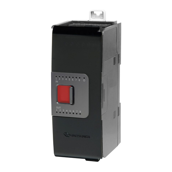
Uni-I/O™ Modules
Uni-I/O™ is a family of Input/Output modules that are compatible with the UniStream™ control platform.
This guide provides basic installation information for UID-0808R, UID-0808T, UID-0808THS, UID-1600,
UID-0016R, and UID-0016T modules.
Technical specifications may be downloaded from the Unitronics website.
The UniStream™ platform comprises
CPU controllers, HMI panels, and local
I/O modules
that snap together to form an
all-in-one Programmable Logic
Controller (PLC).
Install Uni-I/O™ modules:
▪ Onto the back of any UniStream™ HMI
Panel comprising a CPU-for-Panel.
Onto a DIN-rail, using a
▪
Local Expansion Kit.
The maximum number of Uni-I/O™ modules that can be connected to a single CPU controller is limited.
For details, please refer to the specification sheets of the UniStream™ CPU or any of the relevant Local
Expansion Kits.
Before You Begin
Before installing the device, the installer must:
▪ Read and understand this document.
▪ Verify the Kit Contents.
Installation option requirements
If you are installing a Uni-I/O™ module onto:
▪ A UniStream™ HMI Panel; the Panel must comprise a CPU-for-Panel, installed according to the CPU-for-
Panel installation guide.
A DIN-rail; you must use a Local Expansion Kit, available by separate order, to integrate the Uni-I/O™
▪
modules on the DIN-rail into a UniStream™ control system.
Alert Symbols and General Restrictions
When any of the following symbols appear, read the associated information carefully.
Symbol
Meaning
Danger
Warning
Caution
Caution
▪ All examples and diagrams are intended to aid understanding, and do not guarantee operation. Unitronics
accepts no responsibility for actual use of this product based on these examples.
▪ Please dispose of this product according to local and national standards and regulations.
▪ This product should be installed only by qualified personnel.
▪ Failure to comply with appropriate safety guidelines can cause severe injury or property damage.
▪ Do not attempt to use this device with parameters that exceed permissible levels.
▪ Do not connect/disconnect the device when power is on.
Unitronics
User Guide
UID-0808R, UID-0808T, UID-0808THS
UID-1600, UID-0016R, UID-0016T
The identified danger causes physical and property damage.
The identified danger could cause physical and property damage.
Description
Use caution.
1
Advertisement

Related Manuals for Unitronics UID-0016T


Summarization of Contents
Uni-I/O™ Modules User Guide
Installation Overview
Details on how Uni-I/O™™ modules attach to HMI panels or DIN-rails.
Pre-Installation Checks
Essential steps before installing Uni-I/O™™ modules, including document review and kit verification.
Safety Symbols and Restrictions
Explanation of alert symbols and important general restrictions for safe operation and handling.
Environmental and Kit Information
Environmental Considerations
Guidelines for optimal operating environment, including ventilation and area conditions.
Kit Contents and Module Diagram
Lists items included in the Uni-I/O™™ kit and identifies key components in the module diagram.
Module Connection and Installation
I/O Bus Connector Details
Information on Uni-I/O™™ bus connectors, their purpose, and connection points.
Installing onto HMI Panel
Step-by-step guide for attaching a Uni-I/O™™ module to a UniStream™™ HMI Panel.
Removing a Module
Procedure for safely detaching a Uni-I/O™™ module from its connection.
DIN-rail Installation and Safety Compliance
DIN-rail Installation Guide
Instructions for installing Uni-I/O™™ modules on a DIN-rail using a Local Expansion Kit.
Module Numbering and Identification
Guidance on using provided stickers to number Uni-I/O™™ modules for identification.
UL Compliance and Hazardous Locations
Information on UL listing for hazardous and ordinary locations, including safety precautions.
Wiring Best Practices
General Wiring Precautions
Essential safety measures and best practices for wiring Uni-I/O™™ modules, including power and connections.
Wiring Procedure Details
Step-by-step instructions for preparing and connecting wires to terminals using crimp terminals.
Module Connection Diagrams
UID-0808R & UID-0016R Diagrams
Wiring diagrams illustrating input/output and power connection points for UID-0808R and UID-0016R modules.
UID-0808T & UID-0016T Diagrams
Wiring diagrams illustrating input/output and power connection points for UID-0808T and UID-0016T modules.
UID-1600 & UID-0808THS Diagrams
Wiring diagrams illustrating input/output and power connection points for UID-1600 and UID-0808THS modules.
Detailed Input Wiring
General Wiring Practices
Best practices for grounding, wiring signal routing, and system connections to prevent interference.
Input Wiring for Specific Models
Specific input wiring configurations for UID-0808R, UID-0808T, UID-1600, and UID-0808THS modules.
High Speed Input Modes
Configuration details for high-speed inputs, including pin assignments for pulse signals.
Input Modes and Relay Output Power
Input Mode Configurations
Configuration options for input modes, including Quadrature and Pulse/Direction, with wiring examples.
Relay Output Power Supply
Information on the external power supply needed for relay outputs, including safety and connection guidelines.
Output Wiring and Enhancements
Relay and Transistor Output Configurations
Details on output grouping and wiring for relay and transistor output modules.
Enhancing Relay Contact Life
Methods to extend the life of relay contacts and protect against potential damage, like using diodes.
Advanced Output Configurations
Output Configuration Options
Information on configuring outputs for digital or PWM operation, including pin assignments.
High Speed PWM Output Wiring
Specific wiring instructions for high-speed PWM outputs, including cable type and common connection.
Technical Specifications: Inputs
Module Specifications Summary
Summary table of Uni-I/O™™ modules, detailing inputs, outputs, types, and isolation.
Input Specifications by Model
Detailed input specifications including voltage, current, impedance, and filter settings for various models.
UID-0808THS Input Specifications
UID-0808THS Input Details
Detailed input specifications for UID-0808THS, covering types, isolation, voltage, and filter settings.
High Speed Input Modes Details
Technical details on high-speed input modes, including frequency, period, and pulse width for specific configurations.
Technical Specifications: Outputs
Output Specifications by Model
Detailed output specifications for UID-0808R, UID-0016R, UID-0808T, and UID-0016T modules.
Power Supply and Bus Consumption
Information on output power supply requirements and IO/COM bus current consumption for various modules.
UID-0808THS Output Specifications
UID-0808THS Output Details
Detailed output specifications for UID-0808THS, including type, current, voltage, and switching times.
UID-0808THS PWM and Power Specs
Specifications for UID-0808THS PWM output frequency and power supply requirements.
LEDs and Environmental Specifications
LED Indicator Meanings
Explanation of LED indicators for input, output, and status, detailing their states and meanings.
Environmental Operating Conditions
Specifications for environmental conditions, including operating temperature, humidity, shock, and vibration resistance.
Module Dimensions and Weight
Module Weight
Weights for each Uni-I/O™™ module model, provided in kilograms and pounds.
Module Dimensions
Physical dimensions of the Uni-I/O™™ modules, illustrated with top, side, and front views.
Important Notes and Disclaimers
Module Usage Notes
Important considerations regarding relay life expectancy and current consumption for all Uni-I/O™™ modules.
UID-0808THS Specific Notes
Specific notes for the UID-0808THS, including high-speed block usage and PWM output capabilities.
Need help?
Do you have a question about the UID-0016T and is the answer not in the manual?
Questions and answers