Advertisement
Quick Links
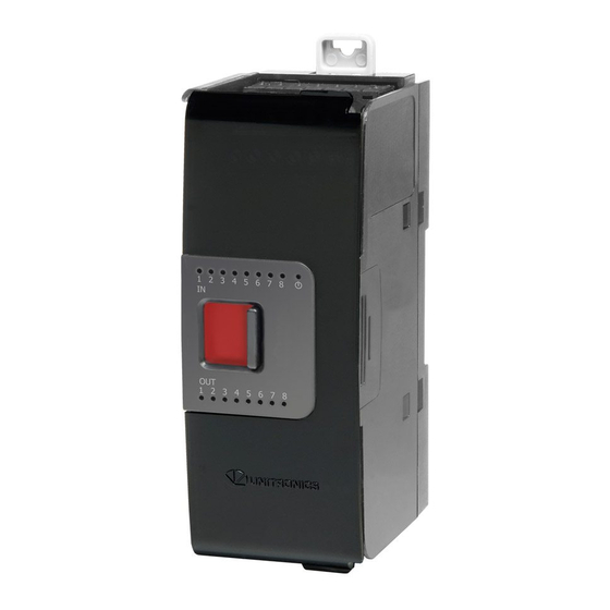
Uni-I/O™ Modules
Uni-I/O™ is a family of Input/Output modules that are compatible with the UniStream™
control platform.
This guide provides basic installation information for the UIS-04PTN and UIS-04PTKN
module.
Technical specifications may be downloaded from the Unitronics website.
The UniStream™ platform
comprises CPU controllers, HMI
panels, and local I/O modules
that snap together to form an
all-in-one Programmable Logic
Controller (PLC).
Install Uni-I/O™ modules:
Onto the back of any
UniStream™ HMI Panel
comprising a CPU-for-Panel.
Onto a DIN-rail, using a
Local Expansion Kit.
The maximum number of Uni-I/O™ modules that can be connected to a single CPU
controller is limited. For details, please refer to the specification sheets of the UniStream™
CPU or any of the relevant Local Expansion Kits.
Before You Begin
Before installing the device, the installer must:
Read and understand this document.
Verify the Kit Contents.
Installation option requirements
If you are installing a Uni-I/O™ module onto:
A UniStream™ HMI Panel; the Panel must comprise a CPU-for-Panel, installed according
to the CPU-for-Panel installation guide.
A DIN-rail; you must use a Local Expansion Kit, available by separate order, to integrate
the Uni-I/O™ modules on the DIN-rail into a UniStream™ control system.
Alert Symbols and General Restrictions
When any of the following symbols appear, read the associated information carefully.
Symbol
Meaning
Danger
Warning
Caution
Caution
All examples and diagrams are intended to aid understanding, and do not guarantee
operation. Unitronics accepts no responsibility for actual use of this product based on
these examples.
Please dispose of this product according to local and national standards and regulations.
This product should be installed only by qualified personnel.
Unitronics
Description
The identified danger causes physical and property damage.
The identified danger could cause physical and property damage.
Use caution.
Installation Guide
UIS-04PTN, UIS-04PTKN
1
Advertisement

Related Manuals for Unitronics Uni-I/O UIS-04PTN


Summary of Contents for Unitronics Uni-I/O UIS-04PTN
- Page 1 Use caution. All examples and diagrams are intended to aid understanding, and do not guarantee operation. Unitronics accepts no responsibility for actual use of this product based on these examples. Please dispose of this product according to local and national standards and regulations.
-
Page 2: Environmental Considerations
Uni-I/O™ module to the CPU or adjacent module. I/O Bus - Right Right-Side Connector, shipped covered. Leave covered when not in use. Bus Connector Cover Inputs 2-3 Input connection points Input LEDs (2-3) Red LEDs Input LEDs (0-1) Red LEDs Status LED Tricolor LED, Green/Red/Orange Unitronics... - Page 3 3. Use the upper and lower guide- tunnels (tongue & groove) to slide the Uni-I/O™ module into place. 4. Verify that the DIN-rail clips located at the top and bottom of the Uni-I/O™ module have snapped onto the DIN-rail. Unitronics...
- Page 4 All power supplies in the system must include double insulation. Power supply outputs must be rated as SELV/PELV/Class 2/Limited Power. Do not connect either the ‘Neutral’ or ‘Line’ signal of the 110/220VAC to device’s 0V point. Do not touch live wires. Unitronics...
- Page 5 Note that the shield must be connected only at one end of the cable; typically, earthing the shield at the Uni-I/O™ end performs better. Keep shield connections as short as possible. Ensure shield continuity when extending shielded cables. Unitronics...
- Page 6 The information in this document reflects products at the date of printing. Unitronics reserves the right, subject to all applicable laws, at any time, at its sole discretion, and without notice, to discontinue or change the features, designs, materials and other specifications of its products, and to either permanently or temporarily withdraw any of the forgoing from the market.
- Page 7 Use caution. All examples and diagrams are intended to aid understanding, and do not guarantee operation. Unitronics accepts no responsibility for actual use of this product based on these examples. Please dispose of this product according to local and national standards and regulations.
- Page 8 Uni-I/O™ module to the CPU or adjacent module. I/O Bus - Right Right-Side Connector, shipped covered. Leave covered when not in use. Bus Connector Cover Inputs 6-7 Input connection points Inputs 4-5 Input LEDs (4-7) Red LEDs Unitronics...
-
Page 9: Installation
3. Use the upper and lower guide- tunnels (tongue & groove) to slide the Uni-I/O™ module into place. 4. Verify that the DIN-rail clips located at the top and bottom of the Uni-I/O™ module have snapped onto the DIN-rail. Unitronics... - Page 10 All power supplies in the system must include double insulation. Power supply outputs must be rated as SELV/PELV/Class 2/Limited Power. Do not connect either the ‘Neutral’ or ‘Line’ signal of the 110/220VAC to device’s 0V point. Do not touch live wires. Unitronics...
- Page 11 Individually connect each functional ground point ( ) to the earth of the system (preferably to the metal cabinet chassis). Use the shortest and thickest wires possible: less than 1m (3.3’) in length, minimum thickness 14 AWG (2 mm Unitronics...
- Page 12 The information in this document reflects products at the date of printing. Unitronics reserves the right, subject to all applicable laws, at any time, at its sole discretion, and without notice, to discontinue or change the features, designs, materials and other specifications of its products, and to either permanently or temporarily withdraw any of the forgoing from the market.
Need help?
Do you have a question about the Uni-I/O UIS-04PTN and is the answer not in the manual?
Questions and answers