Table of Contents
Advertisement
Quick Links
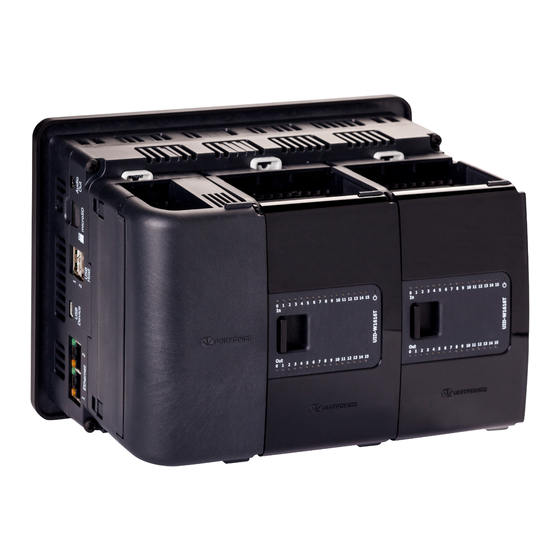
Uni-I/O™ Module
Uni-I/O™ is a family of Input/Output modules that are compatible with the UniStream™
control platform.
This guide provides basic installation information for the UIA-0006 module.
Technical specifications may be downloaded from the Unitronics website.
The UniStream™ platform
comprises CPU controllers, HMI
panels, and local I/O modules
that snap together to form an
all-in-one Programmable Logic
Controller (PLC).
Install Uni-I/O™ modules:
Onto the back of any
UniStream™ HMI Panel
comprising a CPU-for-Panel.
Onto a DIN-rail, using a
Local Expansion Kit.
The maximum number of Uni-I/O™ modules that can be connected to a single CPU
controller is limited. For details, please refer to the specification sheets of the UniStream™
CPU or any of the relevant Local Expansion Kits.
Before You Begin
Before installing the device, the installer must:
Read and understand this document.
Verify the Kit Contents.
Installation option requirements
If you are installing a Uni-I/O™ module onto:
A UniStream™ HMI Panel; the Panel must comprise a CPU-for-Panel, installed according
to the CPU-for-Panel installation guide.
A DIN-rail; you must use a Local Expansion Kit, available by separate order, to integrate
the Uni-I/O™ modules on the DIN-rail into a UniStream™ control system.
Alert Symbols and General Restrictions
When any of the following symbols appear, read the associated information carefully.
Symbol
Meaning
Danger
Warning
Caution
Caution
All examples and diagrams are intended to aid understanding, and do not guarantee
operation. Unitronics accepts no responsibility for actual use of this product based on
these examples.
Please dispose of this product according to local and national standards and regulations.
This product should be installed only by qualified personnel.
Unitronics
Description
The identified danger causes physical and property damage.
The identified danger could cause physical and property damage.
Use caution.
Installation Guide
UIA-0006
1
Advertisement
Table of Contents

Related Manuals for Unitronics Uni-I/O UIA-0006


Summary of Contents for Unitronics Uni-I/O UIA-0006
- Page 1 Use caution. All examples and diagrams are intended to aid understanding, and do not guarantee operation. Unitronics accepts no responsibility for actual use of this product based on these examples. Please dispose of this product according to local and national standards and regulations.
-
Page 2: Environmental Considerations
Uni-I/O™ module to the CPU or adjacent module. I/O Bus - Right Right-Side Connector, shipped covered. Leave covered when not in use. Bus Connector Cover Outputs 4-5 Output connection points Output 3 Outputs 3-5 LEDs Red LEDs Outputs 0-2 LEDs Red LEDs Unitronics... - Page 3 3. Use the upper and lower guide- tunnels (tongue & groove) to slide the Uni-I/O™ module into place. 4. Verify that the DIN-rail clips located at the top and bottom of the Uni-I/O™ module have snapped onto the DIN-rail. Unitronics...
- Page 4 CPU-for-Panel; use these stickers to number the modules. The set contains numbered and blank stickers as shown in the figure to the left. Place them on the modules as shown in the figure to the right. Unitronics...
-
Page 5: Wiring Procedure
UIA-0006 connection points. These points are arranged in four groups of 7 points as shown in the figure to the right. Two top groups Outputs connection points Two bottom groups Outputs and power supply connection points Unitronics... -
Page 6: Wiring Guidelines
Ensure shield continuity when extending shielded cables. For detailed information, refer to the document System Wiring Guidelines, located in the Technical Library in the Unitronics’ website. Wiring the Power Supply This module requires an external 24VDC power supply. In the event of voltage fluctuations or non-conformity to voltage power supply specifications, connect the device to a regulated power supply. -
Page 7: Wiring The Analog Outputs
Do not connect the common point (CM) to the 0V point. Do not use the common points (CM) for any purpose other than connecting the analog output load. Using them for any other purpose may damage the module. Voltage Current Unitronics... - Page 8 UIA-0006 Installation Guide The information in this document reflects products at the date of printing. Unitronics reserves the right, subject to all applicable laws, at any time, at its sole discretion, and without notice, to discontinue or change the features, designs, materials and other specifications of its products, and to either permanently or temporarily withdraw any of the forgoing from the market.
-
Page 9: Before You Begin
Use caution. All examples and diagrams are intended to aid understanding, and do not guarantee operation. Unitronics accepts no responsibility for actual use of this product based on these examples. Please dispose of this product according to local and national standards and regulations. -
Page 10: Kit Contents
Slide the Bus Connector Lock to the left, to electrically connect Lock the Uni-I/O™ module to the CPU or adjacent module. I/O Bus - Right Right-Side Connector, shipped covered. Leave covered when not in use. Bus Connector Cover Output 1 Output connection points Output 0 Unitronics... -
Page 11: Installation
3. Use the upper and lower guide- tunnels (tongue & groove) to slide the Uni-I/O™ module into place. 4. Verify that the DIN-rail clips located at the top and bottom of the Uni-I/O™ module have snapped onto the DIN-rail. Unitronics... - Page 12 All power supplies in the system must include double insulation. Power supply outputs must be rated as SELV/PELV/Class 2/Limited Power. Do not connect either the ‘Neutral’ or ‘Line’ signal of the 110/220VAC to device’s 0V point. Do not touch live wires. Unitronics...
- Page 13 Individually connect each functional ground point ( ) to the earth of the system (preferably to the metal cabinet chassis). Use the shortest and thickest wires possible: less than 1m (3.3’) in length, minimum thickness 14 AWG (2 mm Unitronics...
- Page 14 Ensure shield continuity when extending shielded cables. For detailed information, refer to the document System Wiring Guidelines, located in the Technical Library in the Unitronics’ website. W iring the Power Supply 1 5 B This module requires an external 24VDC power supply.
- Page 15 Uni-I/O™ Current 2-wire 3-wire 4-wire Unitronics...
- Page 16 2 1 B The information in this document reflects products at the date of printing. Unitronics reserves the right, subject to all applicable laws, at any time, at its sole discretion, and without notice, to discontinue or change the features, designs, materials and other specifications of its products, and to either permanently or temporarily withdraw any of the forgoing from the market.
- Page 17 Use caution. All examples and diagrams are intended to aid understanding, and do not guarantee operation. Unitronics accepts no responsibility for actual use of this product based on these examples. Please dispose of this product according to local and national standards and regulations.
- Page 18 Slide the Bus Connector Lock to the left, to electrically connect Lock the Uni-I/O™ module to the CPU or adjacent module. I/O Bus - Right Right-Side Connector, shipped covered. Leave covered when not in use. Bus Connector Cover Inputs 6-7 Input connection points Inputs 4-5 Unitronics...
- Page 19 3. Use the upper and lower guide- tunnels (tongue & groove) to slide the Uni-I/O™ module into place. 4. Verify that the DIN-rail clips located at the top and bottom of the Uni-I/O™ module have snapped onto the DIN-rail. Unitronics...
- Page 20 All power supplies in the system must include double insulation. Power supply outputs must be rated as SELV/PELV/Class 2/Limited Power. Do not connect either the ‘Neutral’ or ‘Line’ signal of the 110/220VAC to device’s 0V point. Do not touch live wires. Unitronics...
- Page 21 Individually connect each functional ground point ( ) to the earth of the system (preferably to the metal cabinet chassis). Use the shortest and thickest wires possible: less than 1m (3.3’) in length, minimum thickness 14 AWG (2 mm Unitronics...
- Page 22 Keep shield connections as short as possible. Ensure shield continuity when extending shielded cables. For detailed information, refer to the document System Wiring Guidelines, located in the Technical Library in the Unitronics’ website. Wiring the Analog Inputs The inputs are not isolated.
- Page 23 Uni-I/O™ Current 2-wire 3-wire 4-wire Unitronics...
- Page 24 UIA-0800N Installation Guide The information in this document reflects products at the date of printing. Unitronics reserves the right, subject to all applicable laws, at any time, at its sole discretion, and without notice, to discontinue or change the features, designs, materials and other specifications of its products, and to either permanently or temporarily withdraw any of the forgoing from the market.
- Page 25 ® Uni-I/O™ is a family of Input/Output modules that are compatible with the UniStream control platform. This guide provides basic installation information for the UIA-0800NH module. Technical specifications may be downloaded from the Unitronics website. ® The UniStream platform comprises CPU controllers, HMI...
- Page 26 UIA-0800NH Installation Guide operation. Unitronics accepts no responsibility for actual use of this product based on these examples. Please dispose of this product according to local and national standards and regulations. This product should be installed only by qualified personnel.
- Page 27 1. Check the unit to which you will connect the Uni-I/O™ module to verify that its Bus Connector is not covered. If the Uni-I/O™ module is to be the last one in the configuration, do not remove the cover of its I/O Bus Connector - Right. Unitronics...
- Page 28 For complete information, please refer to the installation guide of the relevant Local Expansion Kit. Numbering Modules You can number modules for reference purposes. A set of 20 stickers is provided with every CPU-for-Panel; use these stickers to number the modules. Unitronics...
- Page 29 UIA-0800NH connection points. These points are arranged in four groups of 7 points as shown in the figure to the right. Two top groups Input connection points (0,1,2,3) Two bottom groups Input connection points (4,5,6,7) Unitronics...
- Page 30 Ensure shield continuity when extending shielded cables. For detailed information, refer to the document System Wiring Guidelines, located in the Technical Library in the Unitronics’ website. Wiring the Analog Inputs The inputs are not isolated. Each input has its own common point (CM0 for I0, etc.).
- Page 31 Uni-I/O™ 4-wire Unitronics...
- Page 32 UIA-0800NH Installation Guide The information in this document reflects products at the date of printing. Unitronics reserves the right, subject to all applicable laws, at any time, at its sole discretion, and without notice, to discontinue or change the features, designs, materials and other specifications of its products, and to either permanently or temporarily withdraw any of the forgoing from the market.
Need help?
Do you have a question about the Uni-I/O UIA-0006 and is the answer not in the manual?
Questions and answers