Advertisement
Quick Links
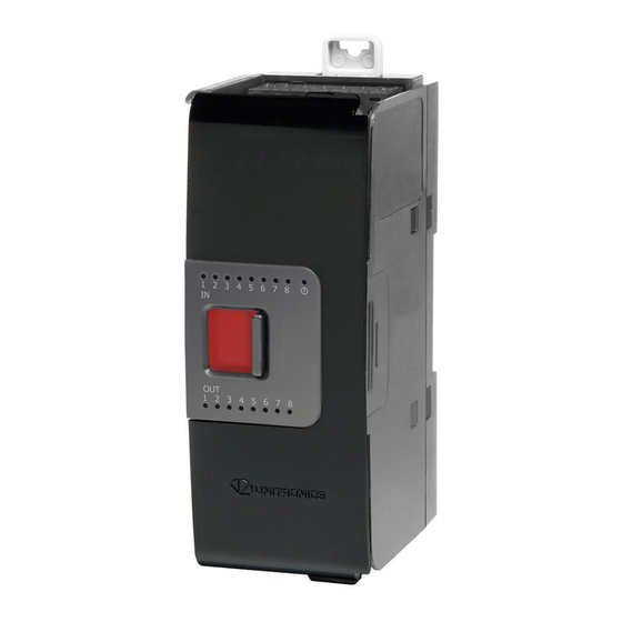
Uni-I/O™ Module
Uni-I/O™ is a family of Input/Output modules that are compatible with the UniStream™ control platform.
This guide provides basic installation information for the UIA-0006 module.
Technical specifications may be downloaded from the Unitronics website.
The UniStream™ platform comprises
CPU controllers, HMI panels, and local
I/O modules
that snap together to form an
all-in-one Programmable Logic Controller
(PLC).
Install Uni-I/O™ modules:
▪ Onto the back of any UniStream™ HMI Panel
comprising a CPU-for-Panel.
▪ Onto a DIN-rail, using a
Local Expansion Kit.
The maximum number of Uni-I/O™ modules that can be connected to a single CPU controller is limited.
For details, please refer to the specification sheets of the UniStream™ CPU or any of the relevant Local
Expansion Kits.
Before You Begin
Before installing the device, the installer must:
▪ Read and understand this document.
▪ Verify the Kit Contents.
Installation option requirements
If you are installing a Uni-I/O™ module onto:
▪ A UniStream™ HMI Panel; the Panel must comprise a CPU-for-Panel, installed according to the CPU-for-Panel installation guide.
▪ A DIN-rail; you must use a Local Expansion Kit, available by separate order, to integrate the Uni-I/O™ modules on the DIN-rail
into a UniStream™ control system.
Alert Symbols and General Restrictions
When any of the following symbols appear, read the associated information carefully.
Symbol
Caution
▪ All examples and diagrams are intended to aid understanding, and do not guarantee operation. Unitronics
accepts no responsibility for actual use of this product based on these examples.
▪ Please dispose of this product according to local and national standards and regulations.
▪ This product should be installed only by qualified personnel.
▪ Failure to comply with appropriate safety guidelines can cause
severe injury or property damage.
▪ Do not attempt to use this device with parameters that exceed
permissible levels.
▪ Do not connect/disconnect the device when power is on.
Unitronics
Meaning
Description
Danger
The identified danger causes physical and property damage.
Warning
The identified danger could cause physical and property damage.
Caution
Use caution.
User Guide
UIA-0006
1
Advertisement

Related Manuals for Unitronics UIA-0006


Summary of Contents for Unitronics UIA-0006
- Page 1 Caution Use caution. ▪ All examples and diagrams are intended to aid understanding, and do not guarantee operation. Unitronics accepts no responsibility for actual use of this product based on these examples. ▪ Please dispose of this product according to local and national standards and regulations.
- Page 2 ▪ Do not allow debris to fall inside the unit during installation. ▪ Install at maximum distance from high-voltage cables and power equipment. Kit Contents ▪ 1 UIA-0006 module ▪ 4 I/O terminal blocks (2 black and 2 gray) UIA-0006 Diagram DIN-rail clips Provide physical support for CPU and modules.
- Page 3 On the Uni-I/O™ module, pull the top DIN-rail clip up and the bottom clip down. Open the door of the Uni-I/O™ and hold it with two fingers as shown in the figure on page 3; then pull it carefully from its place. Unitronics...
- Page 4 Certification UL des automates programmables, pour une utilisation en environnement à risques, Class I, Division 2, Groups A, B, C et D. Cette note fait référence à tous les produits Unitronics portant le symbole UL - produits qui ont été certifiés pour une utilisation dans des endroits dangereux, Classe I, Division 2, Groupes A, B, C et D.
- Page 5 4. Tighten enough to keep the wire from pulling free. UIA-0006 Connection Points All wiring diagrams and instructions in this document refer to the UIA-0006 connection points. These points are arranged in four groups of 7 points as shown in the figure to the right.
- Page 6 Connect the cable shield to the earth of the system - preferably to the metal cabinet chassis. Note that the ➢ shield must be connected only at one end of the cable; typically, earthing the shield at the UIA-0006 end performs better.
- Page 7 User Guide Voltage Current Technical Specifications This guide provides specifications for Unitronics’ Uni-I/O™ module UIA-0006. This module comprises: • 6 analog outputs, 13/14 bit Uni-I/O modules are compatible with UniStream™ family of Programmable Logic Controllers. They may be either snapped onto the back of a UniStream™ HMI Panel next to a CPU-for-Panel to create an all- in-one HMI + PLC controller, or installed on a standard DIN Rail using a Local Expansion Adapter.
- Page 8 Supply voltage is low or missing Slow blink No IO exchange Rapid blink Communication error Orange Rapid Blink OS Upgrade Environmental Protection IP20, NEMA1 Operating -20°C to 55°C (-4°F to 131°F) temperature Storage temperature -30°C to 70°C (-22°F to 158°F) Unitronics...
- Page 9 Operating altitude 2,000 m (6,562 ft) Shock IEC 60068-2-27, 15G, 11ms duration Vibration IEC 60068-2-6, 5Hz to 8.4Hz, 3.5mm constant amplitude, 8.4Hz to 150Hz, 1G acceleration Dimensions Weight 0.17 Kg (0.375 lb) Size Refer to the images below Top View Unitronics...
- Page 10 The tradenames, trademarks, logos and service marks presented in this document, including their design, are the property of Unitronics (1989) (R"G) Ltd. or other third parties and you are not permitted to use them without the prior written consent of Unitronics or such third party as may own them.
Need help?
Do you have a question about the UIA-0006 and is the answer not in the manual?
Questions and answers