
Related Manuals for Unitronics UG-ULK-EIP-4A4BP6


Summary of Contents for Unitronics UG-ULK-EIP-4A4BP6
- Page 1 ® UNITRONICS User Guide UG_ULK-EIP-4A4BP6 IO-LINK (IO-Link MASTER,4A4B,EIP,IP67) User Manual User Manual...
-
Page 2: Table Of Contents
UG_ULK-EIP-4A4BP6 Content 1. INTRODUCTION ........................2 1.1 A ....................... 3 GREEMENT : ..3 HE FOLLOWING TERMS ABBREVIATIONS ARE USED SYNONYMOUSLY IN THIS DOCUMENT IOL: IO-L ; ........................3 LSB: ; .................... 3 LEAST SIGNIFICANT BIT MSB: ; .................... 3 MOST SIGNIFICANT BIT 1.2 P ........................ -
Page 3: Introduction
UG_ULK-EIP-4A4BP6 1. Introduction 1.1 Agreement The following terms/abbreviations are used synonymously in this document: IOL: IO-Link. LSB: least significant bit. MSB: most significant bit. This device: equivalent to "this product", refers to the product model or series described in this manual. 1.2 Purpose This manual contains all the information required to use the device correctly, including information on necessary functions, performance, usage, etc. -
Page 4: Safety Instructions
UG_ULK-EIP-4A4BP6 2. Safety Instructions 2.1 Safety Symbols Read these instructions carefully and inspect the equipment before attempting to install, operate, repair, or maintain it. The following special messages may appear throughout this document or on the equipment to indicate status information or to warn of potential hazards. -
Page 5: General Safety
UG_ULK-EIP-4A4BP6 2.2 General Safety This equipment should only be installed, operated, serviced and maintained by qualified personnel. Qualified person is a person who has skills and knowledge concerning the construction and operation of electrical equipment, and its installation, and has received safety training to recognize and avoid the hazards involved. There shall be a statement in the instructions that if the equipment is used in a manner not specified by the manufacturer, the protection provided by the equipment may be impaired. -
Page 6: Product Overview
UG_ULK-EIP-4A4BP6 3. Product Overview The IO-Link master establishes the connection between the IO-Link device and the automation system. As an integral part of the I/O system, the IO-Link master station is either installed in the control cabinet, or directly installed on site as a remote I/O, and its encapsulation level is IP65/67. -
Page 7: Technical Parameters
UG_ULK-EIP-4A4BP6 4. Technical Parameters 4.1 ULK-EIP-4A4BP6 4.1.1 ULK-EIP-4A4BP6 Specification technical specifications of are as follows: ULK-EIP-4A4BP6... - Page 8 UG_ULK-EIP-4A4BP6...
-
Page 9: Ulk-Eip-4A4Bp6 Led Definition
UG_ULK-EIP-4A4BP6 4.1.2 ULK-EIP-4A4BP6 LED Definition ULK-EIP-4A4BP6 is shown in the below figure. - Page 10 UG_ULK-EIP-4A4BP6 Module Indicator Status Solution green: normal power supply red:power reversed/UA power not connected/too low/high check power wiring voltage green: normal channel signal red: port power supply short check pin 2 and pin 3 circuit (2, 3 pins) check the network green:normal link but abnormal data configuration yellow flash:normal link and...
-
Page 11: Ulk-Eip-4A4Bp6 Dimension
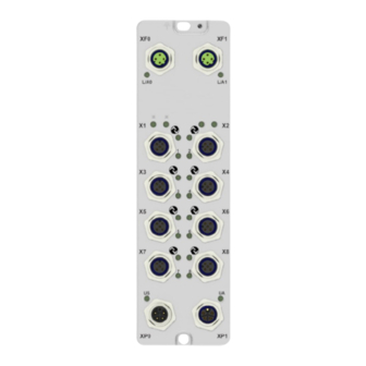
UG_ULK-EIP-4A4BP6 4.1.3 ULK-EIP-4A4BP6 Dimension The size of the ULK-EIP-4A4BP6 is 205mm×60mm×34.5mm, including one φ4.5mm and one φ5.5mm mounting hole, the depth of the mounting hole is 20mm, as shown in the figure below: L/A0 L/A1 4000**** MAC.**:**:**:**:**:**... -
Page 12: Product Installation
UG_ULK-EIP-4A4BP6 5. Product Installation 5.1 Installation Precautions To prevent product malfunction, malfunction, or negative impact on performance and equipment, please observe the following items. 5.1.1 Installation Site Please avoid installing near devices with high heat dissipation (heaters, transformers, large-capacity resistors, etc.) Please avoid installing it near equipment with serious electromagnetic interference (large motors, transformers, transceivers,... -
Page 13: Hardware Interface
UG_ULK-EIP-4A4BP6 5.2 Hardware Interface 5.2.1 ULK-EIP-4A4BP6 Interface Definition Power Port Definition 1. ULK-EIP-4A4BP6 Port Definition The power port uses a 5-pin connector, and the pins are defined as follows: Note: Us is the system power and input power, and Ua is the output power. The power supply must be a limiting power source or class 2 power supply. -
Page 14: Ulk-Eip-4A4Bp6 Wiring Diagram
UG_ULK-EIP-4A4BP6 IO-Link Port Definition The IO-Link port uses a 5-pin connector, and the pins are defined as follows: Use Copper Conductors Only. The maximum input current per port load is 200mA . The voltage range of the output signal and Ua has always been 18~30Vdc . 5.2.2 ULK-EIP-4A4BP6 Wiring Diagram PNP type input signal, that is, the jack is connected to 1 input sensor, which is divided into two-wire sensor and three-wire sensors . -
Page 15: Ulk-Eip-4A4Bp6 Io Signal Address Correspondence Table
UG_ULK-EIP-4A4BP6 3. The IO-Link port is connected to the ULK-EIP-4A4BP6 substation. (When the IO-Link device is an input type, the 2 pins allow no wiring. 5.2.3 ULK-EIP-4A4BP6 IO Process Image Area Allocation 8-way IO-Link Interface (4 Class-A, 4 Class-B) Note: When the IO-Link master port is connected to a slave station with output function, it is necessary to set the Pin2 output point to ON to provide power for the IO-Link device. - Page 16 The tradenames, trademarks, logos and service marks presented in this document, including their design, are the property of Unitronics (1989) (R"G) Ltd. or other third parties and you are not permitted to use them without the prior written consent of Unitronics or such third party as may own them.
Need help?
Do you have a question about the UG-ULK-EIP-4A4BP6 and is the answer not in the manual?
Questions and answers