
Related Manuals for Secutron MR-400


Summary of Contents for Secutron MR-400
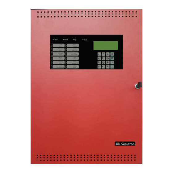
- Page 1 MR-400 Fire Alarm Control Panel LT-6671SEC Rev. 1 Installation and Operation Manual January 2022...
-
Page 3: Table Of Contents
Table of Contents FCC Notice Notice for all MR-400 Series Built-in UDACTs Sold in the U.S.A........FCC Notice ........................Introduction The MR-400 Addressable Fire Alarm Control Panel ............General Notes ........................ MR-400 Overview MR-400 Fire Alarm Control Panel .................. - Page 4 Appendix B - Manual Panel Configuration 10.0 Appendix C - Reporting 10.1 Ademco Contact-ID MR-400 Series Event Codes ............10.2 Security Industries Association SIA Format Protocol MR-400 Series Event Codes ..11.0 Appendix D - Specifications 11.1 MR-400 Fire Alarm Control Panel .................. 11.2 MR-400 System Modules and Annunciator Specifications ..........
- Page 5 Figure 18 RTI-1 Common Remote Trouble Indicator Wiring ............Figure 19 Wiring the Dialer ......................Figure 20 Connecting an MR-400 FACP to a 3G4010CF Interface Device outside Canada ..Figure 21 Connecting an MR-400 FACP to a SLE-LTEV or SLE-LTEA Interface Device outside Canada ..........................
- Page 6 Table 16 Compatible DACR Receivers ..................Table 17 Contact-ID Event Codes ....................Table 18 SIA-DCS Event Codes ....................Table 19 MR-400 Fire Alarm Control Panel Specifications ............Table 20 MR-400 System Modules and Annunciator Specifications ..........Table 21 Recommended Batteries ....................
-
Page 7: Fcc Notice
Notice for all MR-400 Series Built-in UDACTs Sold in the U.S.A. Notes: The Ringer Equivalence Number (REN) assigned to each terminal device provides an indication of the maximum number of terminals allowed to be connected to a telephone interface. - Page 8 Communicator, they should be performed by Secutron Technologies Ltd. or an authorized representative of Secutron Technologies Ltd. For information contact Secutron Technologies Ltd. at the address and phone numbers shown on the back page of this document.
-
Page 9: Introduction
Semi-flush or surface mountable enclosures for retrofits and new installations. Note: Installation of the MR-400 Fire Alarm Control panel should be in accordance with National Electrical Code NFPA 70 and NFPA 72. Final acceptance subject to the Local Authority Having Jurisdiction (AHJ). -
Page 10: General Notes
Zone/Group Is a logical concept for a Fire Alarm Protected Area, and will consist of at least one Circuit. The MR-400 uses Groups extensively to facilitate bypass of multiple input and output points. Display Points The MR-400 LCD display annunciates the status of the system and connected devices. -
Page 11: Mr-400 Overview
MR-400 Overview This chapter lists all the possible components of an MR-400 fire alarm control system. MR-400 Fire Alarm Control Panel The MR-400 Fire Alarm Control Panel has the following features: • Main Board, Power Supply and Backbox. • Main Display with 4 x 20 LCD display. -
Page 12: Mr-400 System Components
MR-400 System Components The following table describes the components of the MR-400 Fire Alarm Control system. Table 1 MR-400 FACP System Components Model Description Model MR-400, black backbox, red door MR-400 enclosure comes complete with main board, power supply, transformer and main display. - Page 13 Table 1 MR-400 FACP System Components (Continued) Model Description Smart Relay Module with White Enclosure. MR-2312-SW12 Can support up to 12 relays. Smart Relay Module with Red Enclosure. MR-2312-SR12 Can support up to 12 relays. 32 point Remote Annunciator with 32 RAM-1032TZDS Trouble LEDs.
- Page 14 Table 1 MR-400 FACP System Components (Continued) Model Description AGD-048 Graphic Annunciator Adder Driver Board. Common Remote Trouble Indicator, Buzzer RTI-1 and LED. MMX-BB-1001D White Enclosure for one annunciator. MMX-BB- Red Enclosure for one annunciator. 1001DR MMX-BB-1002D White Enclosure for two annunciators.
-
Page 15: Table 2 Mgc Mix-4000 Series Compatible Addressable Devices
3.2.1 Devices The following table lists all the devices available for the MR-400 FACP. Table 2 MGC MIX-4000 Series Compatible Addressable Devices MGC Addressable Detectors and Control Modules MGC Addressable Detectors MIX-4010 Photoelectric Smoke Sensor MIX-4010-ISO Photoelectric Smoke Sensor with Built-in Short Circuit Isolator... -
Page 16: Installation
Installation This chapter describes the installation of the MR-400. Mechanical Installation The MR-400 is suitable for flush or surface mounting with a built-in trim ring. Dimensions of Enclosure (minus built in trim ring) 14.5” x 4.25” x 21” Distance between horizontal mounting screws 12”... -
Page 17: Installation Tips
Installation Tips 1. Group the incoming wires through the top of the enclosure. For easy identification and neatness use a wire tie to group wires. 2. Be sure to connect a solid Earth Ground (from building system ground / to a cold water pipe) to the Chassis Earth Ground Mounting Lug, and to connect the Earth Ground Wire Lugs from the Main Chassis to the ground screw on the backbox. -
Page 18: Connections And Jumpers
Connections and Jumpers JW11 Main Board JW10 Core Board Buzzer JW12 JW14 Figure 3 Port and Jumper Locations on Main Board... -
Page 19: Table 3 Main Board Connectors And Jumpers
Table 3 Main Board Connectors and Jumpers Connector/ Description Jumper To Power Supply To Power Supply Ribbon Cable connects to P4 of front display To PC Configurator Factory Use Only To PR-300 To Printer NOT USED Factory Use Only USB Port to PC Configurator Future Use Must be ON (default) - Allows Configuration Connection Must be ON (default) - Annunciator End of Line... -
Page 20: Installing Adder Modules
Figure 4 Jumper on back of display Installing Adder Modules The MR-400 Fire Alarm Control panel is shipped pre-assembled with all main components and boards. The following items can be installed in the field: • PR-300 Polarity Reversal And City Tie Module •... -
Page 21: Figure 5 Main Board With All Modules Installed
See the following diagrams for adder module installation locations. For Jumper or DIP Switch settings refer to Table 3 and for Wiring Specifications see 7.1 Wiring Tables. Barrier Terminal Block TR-061Transformer MR-400 Main Board MD-819 Power Supply Board PR-300 or PCS-100 mounts on the right-hand side... -
Page 22: Figure 6 Installing The Pr-300 Polarity Reversal And City Tie Module
Table 5 PR-300 Polarity Reversal and City Tie Module Connectors and Jumpers Item Setting Connect cable to P8 on the Main Board of the MR-400 Not used. Keep jumper intact. Note: If using a PR-300 remember to remove JW7 on the main board. For the location... -
Page 23: Operation
• The maximum number of isolators is determined by the loop current. • The MR-400 FACP will test the sensitivity of a single sensor address every 4 minutes. Each address will be tested once, approximately every 11 hours. 5.1.1 Supervision of Devices... -
Page 24: Figure 7 Mgc-3000 Configurator Date And Time Settings
5.1.2 Device LEDs • Polling the devices on the loop causes the device LED to flash normally. • All device LEDs can be suppressed via the configurator. Suppressing the device LEDs causes sounder or relay bases to not operate. For an unconfigured device, the LED will be steadily red. -
Page 25: Configurable Input Types
going dirty according to the gradual change in the normal clean air value received. When it can no longer compensate for an increasingly dirty detector, a dirty detector trouble is indicated for that device. 5.1.5 Auto Test Periodically each detector is commanded to return an alarm value to test its ability to alarm. If the device fails the test, a trouble is indicated on that device. - Page 26 Table 7 Configurable Input Types (Continued) Device Types Dual Input Module Description Mini Dual Input Module Detectors As listed in located in Conventional Zone Input Type Configurator Section number Module Verified Alarm Verified Alm 5.2.12 5.2.1 Alarm Input (Non-Verified) An un-bypassed, non-verified alarm input entering into alarm, activates the common alarm sequence.
- Page 27 • A normal to off-normal status change indication shall be latched and only manually resettable at the control unit or display and control centre. 5.2.3 Building/Property Safety Input Building/Property Safety Inputs may include but are not limited to: fan status, dampers, motors, elevators, telephones, etc.
- Page 28 5.2.6 Waterflow Alarm Input Waterflow inputs are sampled every second. 10 samples in alarm in any given 15 second period confirms the alarm condition. Therefore from a continuous input activation the alarm will be processed within 10s. LED Indication The Alarm Zone LED indicator flashes when one sample indicates an alarm condition. If the alarm is confirmed the LED indicator will illuminate steady.
-
Page 29: Output Types
5.2.11 Auto Day/Night Configures (mini) dual input modules for auto day/night alarm thresholds. For more information on alarm thresholds see 5.1.3 Alarm Conditions. 5.2.12 Verified Alarm Input Un-bypassed verified alarm inputs entering into alarm are verified over a period of time to determine if the alarm condition is valid. -
Page 30: Nac Circuit Operation
Additional Operation Features • The panel can synchronize strobes directly without the use of the synchronous module. • Depending on the device, the system can detect open and short troubles and report it as an output circuit trouble. 5.3.1 Signal Output For audible devices such as bells and piezo mini-horns. -
Page 31: Single Stage Operation
Powered output circuits are supervised while they are not active for both open circuits and shorts. The circuit will not be activated if there is a short trouble on the circuit. It will be activated if an open trouble is indicated. A circuit trouble activates the common trouble sequence as a non- latching trouble. -
Page 32: Evacuation Codes
• Activates at the evacuation rate any additional non-disconnected signals associated with the new input. Evacuation Codes The following Evacuation codes can be configured for the MR-400 FACP. Continuous On 100% of the time. Temporal Code 0.5 second on and 0.5 second off repeated 3 times 1.5s pause March Code 0.5 second on 0.5 second off. -
Page 33: Figure 8 Enabling The Positive Alarm Sequence
• The buzzer remains silenced. • Common Alarm LED turns OFF. • Individual zone LED (if programmed) turns OFF. • Cancels the alarm event with no log reference. • Fire alarm system returns to normal. If at any time during the Positive Alarm Sequence a second alarm (PAS or otherwise) is actuated or the given time limits expire, the fire alarm will go into evacuation mode and the following occurs: •... -
Page 34: Remote Annunciator Operation
In the Job Details window, check the Positive Alarm Sequence box. This option only applies to alarm input devices with the PA flag (F2) set. Remote Annunciator Operation The MR-400 Fire Alarm Control Panel supports the following types of annunciators • RAX-LCD-LITE shared display annunciator. -
Page 35: Dialer Operation
Supervised as one of the (maximum) seven permitted annunciators. Dialer Operation The MR-400 is equipped with a built-in dialer. The dialer provides a means to communicate panel status to the remote central monitoring station using two dedicated phone lines. The two standard protocols for communicating with the central monitoring station are supported by this panel are as follows. -
Page 36: Using The Operation Menu From The Control Panel
5.10 Using the Operation Menu from the Control Panel Operations of the MR-400 Addressable Fire Alarm Control Panel can be managed via the Operation Menu on the LCD Shared Display. Accessing the menus is done via the Numeric Keypad and Cursor Buttons. For a complete description of how to use the Numeric Keypad and Cursor Buttons see Numeric Keypad and Cursor Buttons on page 51. -
Page 37: Figure 9 Operation Menu
• Ground Fault Testing - Factory Use Only Complete configuration of the system is done via the MGC-3000 software configurator. How to Enter the Operation Menu 1. Press the Menu button. 2. Use the DOWN Cursor key to scroll to 3. Operation and press the Enter button to enter the Operation Menu. - Page 38 Sets the password for all three access levels. The minimum number of digits for a password is 4. For changing a specific level of password the password required is the equivalent level or higher level. The user is prompted to enter the access level for which the password needs to be changed. Access Level :1 The user is then prompted to enter the current access level or higher level password.
- Page 39 1. Alarm log The alarm log report displays the contents of the alarm event log on the shared display which contains the last 400 of any of the following events: • Activation of any alarm input or common control which activates the common alarm sequence.
- Page 40 Device information consists of the percent of alarm if the device is an input. 1. Enter the loop number of the desired device and press the Enter button. Loop Number Loop :__ The display shows the loop number, device address, the device type, device status, and the level of alarm, in the following format: Loop 1 Address 2 0001 0000 0096 0032...
- Page 41 MP devices. Since parameter values and addresses are not disclosed to the user, this tool is used to report information to Secutron technical support. If the panel is connected to a printer the user will be prompted to select an output source: - Report To - 1.
- Page 42 Once the report is on display it will list all the parameters of all the addresses related to the device. In this display “Crt.” indicates report line number, “Add” indicates device current address, “Parm#” indicates the parameter number from the current address, and “Val#” indicates the parameter value.
- Page 43 • activating any input activates all signals for half a second. • Trouble on any input activates all signals continuously for 5 seconds. After the code is transmitted, the input resets (if resettable) and is tested again. If it is still in alarm or trouble the code will be re-transmitted.
- Page 44 5.10.6 Bypass The bypass operation has the following options: 1. Device/Circuit Individual circuit can be bypassed using this option. The user is prompted for the device’s loop number and the device address to be bypassed. Dev Loop # & Addr Loop :__ DevAddr :___ If the device is not bypassed the user is prompted to bypass the circuit.
- Page 45 Scroll up/down to select group and press Enter. If the group selected is not bypassed the user is prompted to bypass the group. After the confirmation the group is bypassed and the message appears that the group is bypassed. Group Bypassed If the group is already bypassed, the user is prompted to un-bypass the group.
-
Page 46: Table 10 List Bypass Special Characters
4. List Bypass A list of devices may be bypassed using this option. The user is prompted to enter the loop number associated with these devices. Loop number Loop :__ Next enter the address list of devices you wish to bypass. Use the following symbols to enter the address list: Table 10 List Bypass Special Characters Symbol... - Page 47 5. List Unbypass A list of devices can be bypassed using this option. The user is prompted to enter the loop number to be unbypassed. Loop number Loop :__ Enter the list to unbypass, the last list bypassed will be displayed. If the list to be unbypassed is shown, just press Enter to complete the unbypassing.
- Page 48 Aux rly disconnected Reconnect ?Y/N After the confirmation the auxiliary relays are reconnected and the information message is displayed that the auxiliary relays are reconnected. Aux relays Reconnected 5.10.8 Test Dialer Special function is provided to test the dialer operation. This function can manually test both the phone line L1 and L2 and also reset the dialer where all the events to be reported in the queue are cleared and the dialer status is reset.
- Page 49 Verify Counters cleared 5.10.11 Ground Fault Test - Factory Use Only Displays the system ground fault, positive and negative. When ground fault test is selected, your passcode will be requested. An example of a ground fault test result is shown below. 5.10.12 Positive Alarm Sequence If this feature is enabled the system allows for Positive Alarm Sequence alarm signals from...
-
Page 50: Indication & Controls
12 Control buttons with associated LEDs • 16 button Numeric Keypad with Cursor buttons Figure 10 below shows the LED indicators and control buttons on the MR-400 front display. Figure 10 LED Indicators and Control Buttons LCD Display The display is a four line, 20 character back-lit alphanumeric LCD. It displays information regarding the panel, its circuits, and devices. -
Page 51: Figure 11 Numeric Keypad
6.2.1 Numeric Keypad and Cursor Buttons Figure 11 Numeric Keypad Description Key 2 (Up cursor) Press this button to move the cursor or scroll up lists in a continuous loop. Key 4 (Left Cursor) Press this button to move the cursor or select options to the left. Key 6 (Right Cursor) Press this button to move the cursor or select options to the right. -
Page 52: Common Led Indicators And Control Buttons
Common LED Indicators and Control Buttons For complete descriptions of all LED indicators and control buttons see the following table. Table 11 LED Indicators and Control Buttons LED Indicator and Description Control Buttons AC On Indicator Illuminates steady green when the main AC power is within acceptable levels. The LED turns off when the level falls below the power-fail threshold and the panel is switched to standby (battery) power. - Page 53 Table 11 LED Indicators and Control Buttons (Continued) LED Indicator and Description Control Buttons Trouble Queue Button and Indicator Flashes yellow when any trouble condition is detected on the panel. The buzzer sounds at the slow rate. Pressing the Trouble Queue button allows the user to cycle through and review a list of active Troubles from oldest to most recent.
- Page 54 Table 11 LED Indicators and Control Buttons (Continued) LED Indicator and Description Control Buttons General Alarm Button and Indicator When pressed, this button will activate the panel into evacuation. The LED indicator will turn steadily red. Signal Silence Button and Indicator Flashes yellow at the Trouble Flash rate when Indication Circuits are silenced by the following: •...
- Page 55 Table 11 LED Indicators and Control Buttons (Continued) LED Indicator and Description Control Buttons Fire Drill Button and Indicator Illuminates steady yellow during an active Fire Drill. Pressing the Fire Drill button activates all programmed and non-Disconnected Indicating Circuits. It does not transmit any Alarms via the City Tie, or Common Alarm Relay.
-
Page 56: Wiring
Wiring This chapter describes the proper field wiring for the MR-400. Wiring Tables 7.1.1 Addressable Loop Wiring Maximums MGC Devices • Maximum Loop Current = 350 mA • Maximum Loop Resistance = 40 ohms • Maximum Loop Capacitance = 0.5 F •... -
Page 57: Table 14 Conventional Zone Module Input Circuit Wiring Table
Maximum Voltage Drop Should Not Exceed 1.67 Volts 7.1.4 Input Circuits If using conventional detectors in an MR-400 FACP, Secutron MIX-4042 conventional zone modules must be used. Refer to LT-1023SEC for compatible detectors. Table 14 Conventional Zone Module Input Circuit Wiring Table... -
Page 58: Wire Routing
Wire Routing Note: All external connections are power limited except for the AC connections to the transformer. Transformer connections must be routed separately from all other external connections using their own conduit. All power limited wiring shall be routed through remaining knockouts. This knockout is to be used exclusively for AC input. -
Page 59: Addressable Loop Wiring
Addressable Loop Wiring Note: When an SLC device is powered by the AUX output, the supervision of the power pathway shall match the SLC pathway performance requirements. 7.3.1 Addressable Loop Wiring - Class B MULTI-SENSOR DETECTOR OUTPUT MODULE PHOTOELECTRIC SMOKE SENSOR PULL STATION TRI-MODE HEAT DETECTOR... -
Page 60: Nac Circuit Wiring
SENSOR M500X ISOLATOR TRI-MODE HEAT DETECTOR Figure 15 Addressable Loop Wiring - Class X NAC Circuit Wiring The MR-400 Fire Alarm Control Panel supports up to 4 NAC circuits that can be wired as either: • Class B • Class A To supervise each Class B NAC circuit, use a 3.9K End-of-Line resistor. -
Page 61: Figure 16 Nac Circuit - Class B Wiring
7.4.1 NAC Circuit – Class B Wiring CLASS B WIRING CIRCUIT - 1 + + - - NAC1 NAC CIRCUITS #2, #3 AND #4 ARE NOT SHOWN. WIRE AS SHOWN ABOVE. BELL STROBE HORN EOL-392 Figure 16 NAC Circuit – Class B Wiring 7.4.2 NAC Circuit –... -
Page 62: Figure 18 Rti-1 Common Remote Trouble Indicator Wiring
7.4.3 UL 864 Rev. 10 Addressable Supervised Output Module Wiring As per UL864 Rev.10 56.4.3, ensure that a single break, ground or wire-to-wire fault on the installation conductors of a signalling circuit for use with addressable notification appliances or modules shall not affect the operation of more than one notification zone. Exception: Riser conductors installed in accordance with the survivability from attack by fire requirements in National Fire Alarm Code, NFPA 72. -
Page 63: Module And Devices Wiring
Module and Devices Wiring 7.5.1 Dialer Wiring Wire the Dialer to the Public Telephone Switch and premises Telephone as shown in Figure 19. For information on Compatible DACR Receivers see Chapter 8.0 Appendix A - Compatible Receivers. Public Switch Telephone Wiring RJ31X GREEN BROWN... -
Page 64: Figure 20 Connecting An Mr-400 Facp To A 3G4010Cf Interface Device Outside Canada
AC failure trouble and low battery trouble - Install the DSC RM-2 Relays inside the 3G4010CF enclosure above the PS4086 Figure 20 Connecting an MR-400 FACP to a 3G4010CF Interface Device outside Canada Note: The DSC interface device 3G4010CF is required if the installation requires UL864... -
Page 65: Figure 21 Connecting An Mr-400 Facp To A Sle-Ltev Or Sle-Ltea Interface Device Outside Canada
Central Monitoring Station (Example) - All extended wiring must be in metallic conduit - Wiring between FACP and SLE-LTEV or SLE-LTEA: 20 feet max. Figure 21 Connecting an MR-400 FACP to a SLE-LTEV or SLE-LTEA Interface Device outside Canada Note: The NAPCO Starlink interface device SLE-LTEV or SLE-LTEA is required if the installation requires UL864 10th edition certification. -
Page 66: Figure 22 Wiring The Pr-300 Polarity Reversal And City Tie Module
7.5.4 PR-300 Polarity Reversal and City Tie Module Wiring Wire the PR-300 Polarity Reversal and City Tie Module successfully as shown in Figure 22. • Plug PR-300 ribbon cable P1 into connector P8 on the Main Fire Alarm Board. • Remove jumper plug from JW7 on the Main Fire Alarm Board. -
Page 67: Power Supply Wiring
600 volt insulation and proper over current circuit protection that complies with local codes. For the MR-400 Power Supply Electrical Ratings, see Table 15 Power Supply Electrical Ratings and for specifications, see 11.0 Appendix D - Specifications. -
Page 68: Figure 23 Main Power Supply Wiring And Connections
MR-400 Main Board MD-819 Power Supply Board Ribbon Cable Power Connector BLUE BLACK BLACK BATTERY BATTERY Figure 23 Main Power Supply Wiring and Connections 7.6.2 Supervision (Class B) of Auxiliary Supplies Aux 2 Resettable Auxiliary Power (supervised, regulated) The AUX 2 resettable auxiliary power supply is supervised for shorts. -
Page 69: Figure 24 Supervision Of Auxiliary Supplies
This filtered circuit is supervised for shorts. A short will: • Disconnect the power until the “RESET” button is pressed. • Generate a trouble signal The circuit must be supervised for opens utilizing the End of Line Relay Model EOLR-1 as shown in Figure 24. -
Page 70: System Checkout
System Checkout The following are the recommended steps before and during the powering up of the MR-400. 7.7.1 Before Turning The Power ON 1. To prevent sparking, DO NOT connect the batteries first. Connecting the batteries is only to be done after the system has been powered from the main AC Supply. -
Page 71: Appendix A - Compatible Receivers
Appendix A - Compatible Receivers The built-in dialer of the MR-400 Fire Alarm Control Panel is compatible with the following Digital Alarm Communicator Receivers (DACR) listed: Table 16 Compatible DACR Receivers DACR Receiver Model Protocols SurGard MLR2 Multi-Line Receiver (ULI approved) -
Page 72: Appendix B - Manual Panel Configuration
Appendix B - Manual Panel Configuration COMMAND MENU The command menu is the first menu displayed for command mode. The command menu is divided into four main sub menu categories, the configuration allows full front panel configuration of the system and the operation menu performs certain operations which may not be possible using the common control switches and indicators on the front panel. - Page 73 The manual signal silence option will allow silencing of the signal, from the common control signal silence switch, when they are active. Panel Configuration/Features/Fire Drill Fire Drill [x] Enabled This function is used to enable/disable fire drill operation from the fire common control fire drill switch at the front panel.
- Page 74 This feature allows the alarm transmits and auxiliary alarm relay to reset on “SIGNAL SILENCE” rather than the “RESET” switch if enabled. Default is disabled. Panel Configuration/Features/Power fail timer Pwr fail tmr. [x] None [ ] 1 Hr [ ] 2 Hrs [ ] 3 Hrs This feature allows a programmed delay before the AC fail trouble is transmitted by the optional PR-300.
- Page 75 [ ] March Time [x] Temporal [ ] California Select the evacuation code for the 2nd stage in a two stage system and for the 1st stage in a single stage system. Panel Configuration/Features/Building alert Bldg. alert [ ] Enabled Alert sounds for building input activation.
- Page 76 Enter new tag... ______ PANEL CONFIGURATION/4. USER MESSAGE Allows you to edit (change) the FACP Front Panel Message, i.e. “Welcome to Secutron”. PANEL CONFIGURATION/5. LANGUAGE Allows you to select the language of the LCD display. English is the default. To change the language to French, select French in the panel configuration menu, then exit the configuration and then re-enter and select auto default.
- Page 77 COMMAND MENU/ 4. RESET CONFIG The Reset Config feature allows fast configuration of a new site. It detects all connected devices and creates a job file. Use Reset Config to configure the panel for the first time. 1. Wire the MIX-4000 devices to the panel and power up the panel (as described in section 7.7 on page 70).
-
Page 78: Appendix C - Reporting
10.0 Appendix C - Reporting 10.1 Ademco Contact-ID MR-400 Series Event Codes Table 17 Contact-ID Event Codes Event Description Event Qualifier Code Group # Contact # Family Phone Line #1 trouble detected Trouble New event 1 351 Phone Line #2 trouble detected... -
Page 79: Security Industries Association Sia Format Protocol Mr-400 Series Event Codes
10.2 Security Industries Association SIA Format Protocol MR-400 Series Event Codes SIA Format Protocol does not define indicating zone troubles, but lists it as Untyped Zone Trouble/Restore. Table 18 SIA-DCS Event Codes Event Description Event Family Qualifier SIA Event Code Parameter... -
Page 80: Appendix D - Specifications
11.0 Appendix D - Specifications 11.1 MR-400 Fire Alarm Control Panel Table 19 MR-400 Fire Alarm Control Panel Specifications MR-400 Fire Alarm Control Panel General Digital signal processor based design, fully configurable from LCD display with optional password protection. Electrical ratings... -
Page 81: Mr-400 System Modules And Annunciator Specifications
Table 19 MR-400 Fire Alarm Control Panel Specifications (Continued) MR-400 Fire Alarm Control Panel RS-485 port For remote annunciators. Terminals are labelled “RS-485”. Ground Fault 10 K Ohms Impedance Open Circuit Fault 100 K Ohms Short Circuit Fault 0 Ohms... -
Page 82: Appendix E - Battery Calculations
Power Requirements (All currents are in amperes) Total Total Model Number Description Standby Alarm Standby Alarm MR-400 MR-400 FACP with Dialer 0.225 0.430 Remote Annunciator with 4- RAM-3318-LCD 0.070 0.100 line LCD Display Remote Annunciator with 4- RAX-LCD-LITE 0.065 0.080... -
Page 83: Table 21 Recommended Batteries
Total Alarm Current must be 5 amperes or less. NAC Circuits must not exceed 5 amperes. Battery Selection Battery Size = Multiply (C) by 1.20 to derate battery. See the following table for the recommended Secutron batteries for use with this panel Table 21 Recommended Batteries Battery Model... -
Page 84: Warranty And Warning Information
Please read this document CAREFULLY, as it contains important warnings, life-safety, and practical information about all products manufactured by the Mircom Group of Companies, including Mircom and Secutron branded products, which shall include without limitation all fire alarm, nurse call, building automation and access control and card access products (hereinafter individually or collectively, as applicable, referred to as “Mircom System”). - Page 85 The testing should include all sensing devices, keypads, consoles, alarm indicating devices and any other operational devices that are part of the system. NOTE TO USERS: All Mircom Systems have been carefully designed to be as effective as possible. However, there are circumstances where they may not provide protection.
- Page 86 13. Wireless Devices Placement Proximity. Moreover all wireless devices must be a minimum and maximum distance away from large metal objects, such as refrigerators. You are required to consult the specific Mircom System manual and application guide for any maximum distances required between devices and suggested placement of wireless devices for optimal functioning.
- Page 87 CANADA - Main Office U.S.A © Secutron 2022 25 Interchange Way 4575 Witmer Industrial Estates Printed in Canada Subject to change without prior notice Vaughan, ON L4K 5W3 Niagara Falls, NY 14305 Tel: (905) 660-4655 Tel: (905) 660-4655 www.secutron.com (888) 660-4655...
Need help?
Do you have a question about the MR-400 and is the answer not in the manual?
Questions and answers