Table of Contents
Advertisement
Introduction
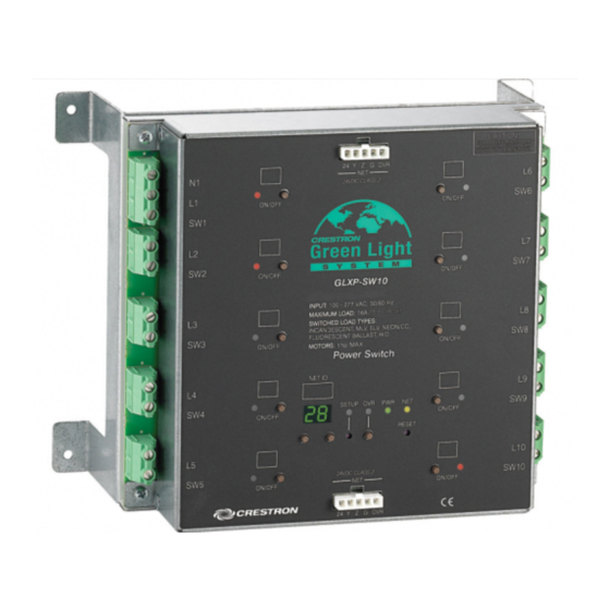
CRESTRON GREEN LIGHT power switching cabinets come pre-configured with GLXP modules already installed.
The cabinets only require installation and wiring of feed and load circuits.
Industry Compliance
The cabinet and modules are Listed to applicable UL Standards and requirements by Underwriters Laboratories Inc.
Application
The following diagram shows CRESTRON GREEN LIGHT cabinets in a lighting application that is controlled by
an IPAC system.
CRESTRON GREEN LIGHT Power Switching Cabinets in a Typical Lighting Application
Crestron Electronics, Inc.
15 Volvo Drive Rockleigh, NJ 07647
Tel: 888.CRESTRON
Fax: 201.767.7576
www.crestron.com
CRESTRON GREEN LIGHT™ Power Switching
(E227280 (cabinet) and E103692 (modules))
Installation Guide – DOC. 6672B
(2020570)
Specifications subject to
change without notice.
10.08
Advertisement
Table of Contents

Subscribe to Our Youtube Channel
Summary of Contents for Crestron CRESTRON GREEN LIGHT Power Switching
-
Page 1: Industry Compliance
Introduction CRESTRON GREEN LIGHT power switching cabinets come pre-configured with GLXP modules already installed. The cabinets only require installation and wiring of feed and load circuits. Industry Compliance The cabinet and modules are Listed to applicable UL Standards and requirements by Underwriters Laboratories Inc. -
Page 2: Physical Description
Power Switching Physical Description This section shows the exterior and interior dimensions of the CRESTRON GREEN LIGHT cabinet. External Dimensions of CRESTRON GREEN LIGHT Power Switching Cabinets 20" (508 mm) OPTIONAL DOOR TECHNICAL KNOCKOUTS, 50 TOTAL (FOR " (19 mm) &... - Page 3 (461 mm) Power Switching 2" 2" (51 mm) (51 mm) 8" (204 mm) " 277 Service 12 Breaker 30 Breaker 7 1/16” 12 1/16” (180 mm) (310 mm) CRESTRON GREEN LIGHT Power Switching • 3 42 Breaker 15 1/16” (383 mm)
-
Page 4: Installation
The ambient temperature range should be 32°F to 104°F (0°C to 40°C). The relative humidity should range from 10% to 90% (non-condensing). Allow adequate clearance in front of the cover for servicing. Mounting Location 4 • CRESTRON GREEN LIGHT Power Switching CRESTRON GREEN LIGHT™ MAXIMUM HEIGHT OF... - Page 5 Connect control wiring (section C of the following diagram) CLASS 2 WIRING ONLY Installation Guide – DOC. 6672B FEED: 3-PHASE 4-WIRE TO LOADS: 2W + GND 16A (MAX) CLASS 2 WIRING ONLY CRESTRON GREEN LIGHT Power Switching • 5 Power Switching...
- Page 6 6-4 AWG (CU or AL) Use copper or aluminum conductors only – rated 75°C. WARNING: Failure to properly tighten lugs may result in poor electrical connection and overheating of the terminals. 6 • CRESTRON GREEN LIGHT Power Switching CRESTRON GREEN LIGHT™ TORQUE...
- Page 7 Power Switching TORQUE STRIP LENGTH 4.43 lb-in 5/16” (0.5 Nm) (8 mm) 4.43 lb-in 5/16” (0.5 Nm) (8 mm) 35 lb-in 5/16” (4.0 Nm) (8 mm) 45-25 lb-in 3/4" (5.1-2.8 Nm) (19 mm) 1.2000 CRESTRON GREEN LIGHT Power Switching • 7...
- Page 8 Wire Gauge and Torque Values TERMINAL CONNECTOR MAX WIRE RANGE 12 AWG POWER 26-12 AWG OVERRIDE 26-12 AWG 8 • CRESTRON GREEN LIGHT Power Switching CRESTRON GREEN LIGHT™ ® connections for interfacing to the rest of the Crestron TORQUE STRIP LENGTH 4.43 lb-in 1/4”...
- Page 9 Low voltage (24 VDC) power must be supplied to the modules either internally via devices connected to the NET port or externally via a Cresnet power supply connected to the POWER port. To power the modules internally from line power, install a jumper from the INT pin on the supplied POWER connector to the EXT pin on the POWER connector as shown in the following diagram.
- Page 10 When properly connected and receiving 24 VDC power externally, the green LED next to the MODULES port will light. When a lighting module is powered from a Cresnet power supply in the absence of line power, the module’s PWR LED will flash.
-
Page 11: Manual Control
To save the state of all of the outputs as an override setting, press and hold the OVR button for three seconds. The OVR LED blinks to indicate the new override settings have been stored. Installation Guide – DOC. 6672B Power Switching CRESTRON GREEN LIGHT Power Switching • 11... - Page 12 Crestron representative must be performed to ensure system operation. Once the cabinet has been wired and the modules have been tested, contact Crestron at 1-888-CRESTRON [1-888-273-7876] to schedule commissioning. 12 • CRESTRON GREEN LIGHT Power Switching CRESTRON GREEN LIGHT™ Installation Guide – DOC. 6672B...
-
Page 13: Problem Solving
Verify polarity of + and - wires at ballasts and shorted. GLXP-DIMFLV8. + or - wires are not connected. Verify polarity of + and - wires at ballasts and GLXP-DIMFLV8. CRESTRON GREEN LIGHT Power Switching • 13 Power Switching CORRECTIVE ACTION... -
Page 14: Appendix A: Setting Module Net Ids
If the SETUP button is not pressed, the Setup mode will time out after one minute activity and the Net ID will revert back to its original value. 14 • CRESTRON GREEN LIGHT Power Switching CRESTRON GREEN LIGHT™ Installation Guide – DOC. 6672B... -
Page 15: Appendix B: Module Specifications
(0º to 40º C) (0º to 40º C) 10% to 90% RH 10% to 90% RH (non-condensing) (non-condensing) 10 BTU/Hr 10 BTU/Hr CRESTRON GREEN LIGHT Power Switching • 15 Power Switching GLXP-HSW12 GLXP-DIMFLV8 12 Channel High- 8 Channel 0-10V Inrush Switch Fluorescent... -
Page 16: Return And Warranty Policies
All brand names, product names and trademarks are the sole property of their respective owners. Windows is a registered trademark of Microsoft Corporation. Windows95/98/Me/XP/Vista and WindowsNT/2000 are trademarks of Microsoft Corporation. 16 • CRESTRON GREEN LIGHT Power Switching CRESTRON GREEN LIGHT™...


Need help?
Do you have a question about the CRESTRON GREEN LIGHT Power Switching and is the answer not in the manual?
Questions and answers