Teltonika FMB641 Quick Manual
Professional gnss/gsm terminal
Hide thumbs
Also See for FMB641:
- First start-up quick start manual (9 pages) ,
- Manual (6 pages) ,
- Quick manual (21 pages)
Table of Contents
Advertisement
Quick Links
Advertisement
Table of Contents

Related Manuals for Teltonika FMB641


Summary of Contents for Teltonika FMB641
- Page 1 FMB641 Quick Manual Professional GNSS/GSM v1.3 terminal...
-
Page 2: Table Of Contents
How to install USB drivers (Windows) ..........7 Configuration (Windows) ..............7 Quick SMS configuration ..............9 Mounting recommendations ............10 LED indications ................. 11 Characteristics .................. 11 Basic characteristics ............... 11 Electrical characteristics ..............13 Safety information ................14 Certification and Approvals ............. 15 Wiki FMB641|... -
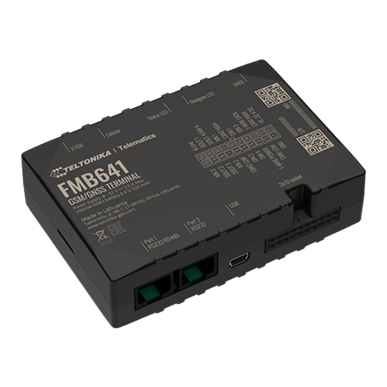
Page 3: Know Your Device
Know your device Figure 1 FMB641 device view Wiki FMB641|... -
Page 4: Pinout
Data channel for Dallas 1-Wire® devices DIN3 Digital input, channel 3 Digital input, channel 1. DEDICATED FOR IGN (DIN1) IGNITION INPUT Figure 2 FMB641 Pinout CAN 2H SAE J1939 CAN interface High channel 2 Analog input, channel 1. Input range: 0-30V/0- AIN1 10V DC Digital output. -
Page 5: Wiring Scheme
Wiring scheme Figure 3 FMB641 Wiring scheme Automotive relay Wiki FMB641|... -
Page 6: Set Up Your Device
4. Connect battery as shown to device. 5. After configuration, see “PC Connection (Windows)”, attach device cover back. 6. Screw in all screws. Device is ready to be mounted. Figure 6 Battery connection Figure 7 Micro-SIM card insert Wiki FMB641|... -
Page 7: Pc Connection (Windows)
PC Connection (Windows) Configuration (Windows) 1. Power-up FMB641 with DC voltage (8 – 32 V) power supply At first FMB641 device will have default factory settings set. These using power wires. LED’s should start blinking, see “LED settings should be changed according to the user's needs. Main indications”. - Page 8 GNSS, GSM, I/O, Maintenance and etc. FMB641 has one user editable profile, which can be loaded and saved to the device. After any modification of configuration the changes need to be saved to device using Save to device button. Main buttons offer following...
-
Page 9: Quick Sms Configuration
2005 – Port • 2006 – Data sending protocol • After successful SMS configuration, FMB641 device will synchronize (0 – TCP, 1 – UDP) time and update records to configured server. Time intervals and default I/O elements can be changed by using... -
Page 10: Mounting Recommendations
▬ Use 3A, 125V external fuse. potentials on the line GND will be unpredictable, which can lead to unstable FMB641 operation and even its failure. Wiki FMB641|... -
Page 11: Led Indications
Characteristics Basic characteristics Table 4 Basic characteristics Table 2 Navigation LED indications Behaviour Meaning Module Name Teltonika TM2500 Permanently switched on GNSS signal is not received Technology GSM ,GPRS, GNSS Blinking every second Normal mode, GNSS is working GNSS GNSS is turned off because:... - Page 12 Sleep, Online Deep Sleep, Deep Sleep At 12V < 250 mA (with full Load/Peak) Configuration and FOTA Web, FOTA, Teltonika Configurator firmware update Interface Digital Inputs Configuration, Events, DOUT Control, Debug Digital Outputs GPRS commands Configuration, Debug, DOUT Control Analog Inputs...
-
Page 13: Electrical Characteristics
Recessive output voltage Input resistance (DIN2) kΩ Differential output voltage Input resistance (DIN3) kΩ Common mode input voltage kΩ Input resistance (DIN4) Supply Input voltage (Recommended Operating voltage Conditions) Input Voltage threshold (DIN1) Input Voltage threshold (DIN2, DIN3, DIN4) Wiki FMB641|... -
Page 14: Safety Information
All related devices is prohibited. must meet the requirements of EN 62368-1 standard. The device FMB641 is not designed as a navigational device for • boats. The device is susceptible to water and humidity. -
Page 15: Certification And Approvals
This sign on the package means that all used electronic and electric equipment should not be mixed with general household waste. Hereby, Teltonika declare under our sole responsibility that the above described product is in conformity with the relevant Community harmonization: European Directive 2014/53/EU (RED). -
Page 16: Warranty
• Repaired • Replaced with a new product • Replaced with an equivalent repaired product fulfilling the same functionality • TELTONIKA can also repair products that are out of warranty at an agreed cost. Wiki FMB641|...
Need help?
Do you have a question about the FMB641 and is the answer not in the manual?
Questions and answers