
Related Manuals for RINGSPANN HW 075 FHM


Summary of Contents for RINGSPANN HW 075 FHM
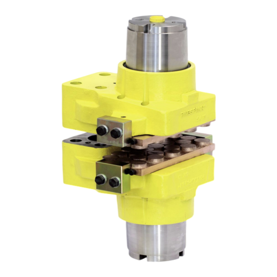
- Page 1 Installation and Operating Instructions for Brake Caliper HW 075 FHM E09.742e Schaberweg 30-38 Telephone +49 6172 275-0 www.ringspann.com 61348 Bad Homburg Telefax +49 6172 275-275 info@ringspann.com Germany...
- Page 2 Disregarding or misinterpreting this installation and operating instructions invalidates any product liability or warranty by RINGSPANN; the same applies if the product is taken apart or changed. These installation and operating instructions should be kept in a safe place and should accompany the product if it is passed on to others –...
-
Page 3: Table Of Contents
Installation and Operating Instructions E 09.742e for Brake Caliper HW 075 FHM spring activated – hydraulic released Date: 16.11.2023 Issue: 7 drawn: BAHS checked: EISF Pages: 23 Page: 3 Contents General notes General safety instructions Special safety instructions Design and function/ parts list... -
Page 4: Spring Activated - Hydraulic Released
Brake torque readjustment is necessary in the event of pad wear. Markings These operating instructions apply: • model brake saddle HW 075 FHM • installation on horizontal brake discs and vertical brake discs in combination with horizontal shafts... -
Page 5: Drawings And Parts Lists
There is a type plate on the brake with a 16-digit article number. The exact design of the brake is defined by this article number only. As well as these instructions, please also consider the catalogue data for the brake at www.ringspann.com and the drawings in the individual sections. Drawings and Parts Lists Fig. 2.1... - Page 6 Installation and Operating Instructions E 09.742e for Brake Caliper HW 075 FHM spring activated – hydraulic released Date: 16.11.2023 Issue: 7 drawn: BAHS checked: EISF Pages: 23 Page: 6 Fig. 2.2...
- Page 7 Installation and Operating Instructions E 09.742e for Brake Caliper HW 075 FHM spring activated – hydraulic released Date: 16.11.2023 Issue: 7 drawn: BAHS checked: EISF Pages: 23 Page: 7 Part Nomenclature Quantity Set Brake pad HW(S) Brake caliper housing for H 075 FHM Cylinder screw M8x10 DIN EN ISO 4762-8.8...
-
Page 8: Intended Use
The brake has been designed for use as a holding, control and stopping brake. Use for any other purpose will be deemed improper. Other uses are improper and incompatible with the specified purpose. RINGSPANN assumes no liability for damages resulting from improper use. The risk is assumed by the user alone. -
Page 9: Handling And Storage
Installation and Operating Instructions E 09.742e for Brake Caliper HW 075 FHM spring activated – hydraulic released Date: 16.11.2023 Issue: 7 drawn: BAHS checked: EISF Pages: 23 Page: 9 Handling and storage The technical data of the brake such as oil pressure, clamping force, oil volume, dimensions and weight are shown on the catalogue pages for the brake. -
Page 10: Installation The Ringspann Brake
Installation and Operating Instructions E 09.742e for Brake Caliper HW 075 FHM spring activated – hydraulic released Date: 16.11.2023 Issue: 7 drawn: BAHS checked: EISF Pages: 23 Page: 10 Installation the RINGSPANN brake General instructions for assembly and installation Before installing the brake, the brake disc must be cleaned with alcohol (e.g. spirit (ethanol) or isopropyl alcohol) or with water-based tenside solutions (soapy water or the like. - Page 11 Installation and Operating Instructions E 09.742e for Brake Caliper HW 075 FHM spring activated – hydraulic released Date: 16.11.2023 Issue: 7 drawn: BAHS checked: EISF Pages: 23 Page: 11 Fig. 8.1 The customer connection part for the brake as well as the brake disc must be checked for dimensional accuracy.
-
Page 12: Setting/ Adjusting The Brake Pad Gap
Installation and Operating Instructions E 09.742e for Brake Caliper HW 075 FHM spring activated – hydraulic released Date: 16.11.2023 Issue: 7 drawn: BAHS checked: EISF Pages: 23 Page: 12 Setting/ adjusting the brake pad gap The distance from both sides of the friction pads to the brake disc should be approx. 1.5 mm when new. - Page 13 Installation and Operating Instructions E 09.742e for Brake Caliper HW 075 FHM spring activated – hydraulic released Date: 16.11.2023 Issue: 7 drawn: BAHS checked: EISF Pages: 23 Page: 13 Caution! The hydraulic actuation of the brake caliper must be carried out in such a way that both caliper halves are actuated simultaneously with the same pressure.
- Page 14 Installation and Operating Instructions E 09.742e for Brake Caliper HW 075 FHM spring activated – hydraulic released Date: 16.11.2023 Issue: 7 drawn: BAHS checked: EISF Pages: 23 Page: 14 Mounting to each of the vent holes measuring a mini connector or an automatic ventilation system.
-
Page 15: Connecting The Signal Cable (Optional For Organic Brake Pads)
As an option, RINGSPANN offers a wear indicator as friction pad wear monitoring for the brakes, which signals when the friction pad wear limit is reached. The indicator lamp in the wear indicator shows that the friction blocks need to be changed. -
Page 16: Start-Up
Installation and Operating Instructions E 09.742e for Brake Caliper HW 075 FHM spring activated – hydraulic released Date: 16.11.2023 Issue: 7 drawn: BAHS checked: EISF Pages: 23 Page: 16 Start-up Prior to commissioning, the caliper to apply pressure and the two safety screws M18x1,5x 60 item 4 to remove. -
Page 17: 11. Maintenance
3 mm is necessary, the brake pads should than be exchanged in pairs. Only original RINGSPANN friction pads may be used. Before replacing the brake pads item 1, ensure that the mass by the brake is secured to prevent... - Page 18 Installation and Operating Instructions E 09.742e for Brake Caliper HW 075 FHM spring activated – hydraulic released Date: 16.11.2023 Issue: 7 drawn: BAHS checked: EISF Pages: 23 Page: 18 Before replacing the friction pads of the brake the caliper hast to be activate with hydraulic pressure.
-
Page 19: Replacing Seals, Strippers And Piston Gaskets
Installation and Operating Instructions E 09.742e for Brake Caliper HW 075 FHM spring activated – hydraulic released Date: 16.11.2023 Issue: 7 drawn: BAHS checked: EISF Pages: 23 Page: 19 Caution! Please note the compression springs are under slight pressure Replacing seals, strippers and piston gaskets Caution! Brake pads must not come in contact with hydraulic fluid. - Page 20 Installation and Operating Instructions E 09.742e for Brake Caliper HW 075 FHM spring activated – hydraulic released Date: 16.11.2023 Issue: 7 drawn: BAHS checked: EISF Pages: 23 Page: 20 Fig. 11.2 Hold or clamp the brake caliper housing item 2 firm in place. Push the brake piston item 14 out of the brake housing.
-
Page 21: 12. Options
Installation and Operating Instructions E 09.742e for Brake Caliper HW 075 FHM spring activated – hydraulic released Date: 16.11.2023 Issue: 7 drawn: BAHS checked: EISF Pages: 23 Page: 21 Fig. 11.3 Please note! Please note brake caliper version standard or special version shortened spring casing. - Page 22 Installation and Operating Instructions E 09.742e for Brake Caliper HW 075 FHM spring activated – hydraulic released Date: 16.11.2023 Issue: 7 drawn: BAHS checked: EISF Pages: 23 Page: 22 Two threaded bores M12x1 are drilled in the brake housing as mounting bores for the inductive proximity switch.
-
Page 23: Drawn: Bahs Checked: Eisf Pages
Installation and Operating Instructions E 09.742e for Brake Caliper HW 075 FHM spring activated – hydraulic released Date: 16.11.2023 Issue: 7 drawn: BAHS checked: EISF Pages: 23 Page: 23 Please note! The inductive proximity sensor must be positioned in such a way that it is damped if the brake is under hydraulic pressure (the LED on the inductive proximity switch glows).
Need help?
Do you have a question about the HW 075 FHM and is the answer not in the manual?
Questions and answers