
Related Manuals for RINGSPANN HW 040 HFA


Summary of Contents for RINGSPANN HW 040 HFA
- Page 1 Installation and Operating Instructions for Brake Calipers HW 040/063/100 HFA E09.611e Schaberweg 30-38 Telephone +49 6172 275-0 www.ringspann.com 61348 Bad Homburg Telefax +49 6172 275-275 mailbox@ringspann.com Germany...
- Page 2 Disregarding or misinterpreting this installation and operating instructions invalidates any product liability or warranty by RINGSPANN; the same applies if the product is taken apart or changed. These installation and operating instructions should be kept in a safe place and should accompany the product if it is passed on to others –...
-
Page 3: Table Of Contents
Impermissible use Condition as delivered Handling and storage Technical prerequisite for reliable operation Installation the RINGSPANN brake General instructions for assembly and installation Assembly and installation Setting/ adjusting the brake pad gap Installing the threaded connection and bleeding the brake... -
Page 4: General Notes
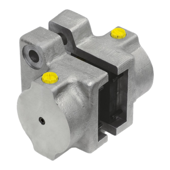
Design and function/ parts list Function The brake calipers HW 040 HFA, HW 063 HFA and HW 100 HFA are machine components used for the purpose of braking accelerated masses safely and reliably. The combination of brake caliper and brake disc provides a complete brake unit capable of securing machines and equipment system effectively. -
Page 5: Drawings And Parts Lists
There is a type plate on the brake with a 16-digit part number. The exact design of the brake is defined by this article number only. As well as these instructions, please also consider the catalogue data for the brake at www.RINGSPANN.com and the drawings in the individual sections. Drawings and Parts Lists Brake calliper HW 040 HFA... - Page 6 Installation and Operating Instructions E 09.611e for Brake Calipers HW 040/063/100 HFA hydraulically activated Date: 19.01.2023 Issue: 18 drawn: BAHS checked: EISF Pages: 21 Page: 6 Part Nomenclature Quantity Part Nomenclature Quantity Circlip Brake housing Shim Piston Grip ring G 6x1 Set brake pad Cylindrical pin 6x20-A-St...
- Page 7 Installation and Operating Instructions E 09.611e for Brake Calipers HW 040/063/100 HFA hydraulically activated Date: 19.01.2023 Issue: 18 drawn: BAHS checked: EISF Pages: 21 Page: 7 Part Nomenclature Quantity Part Nomenclature Quantity Brake housing Circlip Piston Shim 25x35x1 DIN 988 Set brake pad Grip ring G 8x1 Sleeve...
-
Page 8: Intended Use
The brake caliper is designed for use as a holding/parking brake, control brake and/or as stopping brake. Other uses are improper and incompatible with the specified purpose. RINGSPANN assumes no liability for damages resulting from improper use. The risk is assumed by the user alone. -
Page 9: Condition As Delivered
Technical prerequisite for reliable operation Mounting the brake to stable, low-vibration machine components ensures low-screech, low-noise braking. Installation the RINGSPANN brake General instructions for assembly and installation Before installing the brake caliper, the brake disc must be cleaned with alcohol, e.g. ethyl or isopropyl alcohol or a water-based surfactant solution (soapy water, etc.) and then rubbed dry with... -
Page 10: Assembly And Installation
Installation and Operating Instructions E 09.611e for Brake Calipers HW 040/063/100 HFA hydraulically activated Date: 19.01.2023 Issue: 18 drawn: BAHS checked: EISF Pages: 21 Page: 10 Assembly and installation Caution! The brake caliper must not be exposed to hydraulic pressure during assembly/ installation. -
Page 11: Setting/ Adjusting The Brake Pad Gap
Please use screws/bolts of quality grade 10.9 or 12.9 for the standard brake. Type Number of Screw/Bolt Tightening torques* screws/bolts size grade 10.9 grade 12.9 HW 040 HFA M 12 123 Nm 144 Nm HW 063 HFA M 16 302 Nm 354 Nm HW 100 HFA... - Page 12 Caution! Oil expelled from the system must be removed completely. Leaks must be repaired immediately. Connection threading: HW 040 HFA = G 1/4“ HW 063 HFA = G 1/4“ HW 100 HFA = G 3/8“ Hydraulic fluid: Alloyed mineral oil equivalent to Group HLP (DIN 51525 or API classification SC, SD or SE.
-
Page 13: Connecting The Signal Cable (Optional For Organic Brake Pads)
As an option, RINGSPANN offers a wear indicator as friction pad wear monitoring for the brakes, which signals when the friction pad wear limit is reached. The indicator lamp in the wear indicator shows that the friction blocks need to be changed. -
Page 14: Start-Up
Installation and Operating Instructions E 09.611e for Brake Calipers HW 040/063/100 HFA hydraulically activated Date: 19.01.2023 Issue: 18 drawn: BAHS checked: EISF Pages: 21 Page: 14 Start-up The entire surface of both brake pads must be in contact with the brake disc in order to achieve the optimum braking effect. -
Page 15: Maintenance General Maintenance
Caution! Brake pads must always be replaced in pairs. Only original RINGSPANN friction pads may be used. Before replacing the brake pads, ensure that the mass held by the brake is secured to prevent movement, as parts of the brake must be loosened/removed for replacement. - Page 16 Ensure that the hydraulic fluid line is free of residual pressure, e.g. by removing the bleeder plug, as fluid is forced back into the system during brake pad replacement. Replacing brake pads for HW 040 HFA and HW 063 HFA • Remove the holding brackets hold the brake pads in place.
-
Page 17: Replacing Seals, Strippers And Piston Gaskets
Ensure that brake pad material is free of oil and grease. Replacing seals, strippers and piston gaskets Fig. 11.1 HW 040 HFA and HW 063 HFA Fig. 11.2 HW 100 HFA Fig. 11.3 HW 040 HFA and HW 063 HFA Fig. - Page 18 • Press the piston with a press or a plastic hammer into the cylinder bore of the brake housing to the stop point and ensure that it is centred. For HW 040 HFA to HW 100 HFA (with retraction) • Remove the brake caliper and replace the gaskets as described above.
-
Page 19: Installing The Inductive Proximity Switch (Option)
Pages: 21 Page: 19 Piston gaskets: Type Gasket typ Dimension B Gasket part no. (mm) Quad ring with 5134-047003-000000 +0,2 HW 040 HFA support ring 5137-040401-000000 +0,2 Rod gasket 5155-040081-000000 Type B, profile BA Quad ring with 5134-073004-000000 +0,2 support ring... - Page 20 Installation and Operating Instructions E 09.611e for Brake Calipers HW 040/063/100 HFA hydraulically activated Date: 19.01.2023 Issue: 18 drawn: BAHS checked: EISF Pages: 21 Page: 20 Bild 12.1 Switching function: PNP (normally open contact) Switching distance: 2 mm flush Operating voltage: 10..30 V DC Operating current: 0...200 mA...
- Page 21 Installation and Operating Instructions E 09.611e for Brake Calipers HW 040/063/100 HFA hydraulically activated Date: 19.01.2023 Issue: 18 drawn: BAHS checked: EISF Pages: 21 Page: 21 Work sequence for mounting, or in the case that exchanging the inductive proximity switch is necessary with a switching gap of 2 mm: Fig.
Need help?
Do you have a question about the HW 040 HFA and is the answer not in the manual?
Questions and answers