
Related Manuals for Avalue Technology EPC-TGU-B1


Summary of Contents for Avalue Technology EPC-TGU-B1
- Page 1 EPC-TGU-B1 Intel® 11th Gen Tiger Lake Fanless Compact System Quick Reference Guide Ed – 30 August 2023 Copyright Notice Copyright 2023 Avalue Technology Inc., ALL RIGHTS RESERVED. Part No. E2017CAO0A0R...
- Page 2 These answers are normally a lot more detailed than the ones we can give over the phone. So please consult the user’s manual first. To receive the latest version of the user’s manual; please visit our Web site at: http://www.avalue.com.tw/ 2 EPC-TGU-B1 Quick Reference Guide...
-
Page 3: Table Of Contents
2.1.1 Serial port 1/2 connector (COM1/2) ..................14 Installing Hard Disk & Memory (EPC-TGU-B1) ........... 15 Installing M.2 B-Key (2242)/ (3042) card (EPC-TGU-B1) ........17 Installing M.2 E-Key card (EPC-TGU-B1) ............18 Installing M.2 M-Key (2242) card (EPC-TGU-B1) ..........19 Installing Mounting Brackets (EPC-TGU-B1) ............ - Page 4 Boot ............................59 3.6.6 Save and exit ......................... 60 3.6.6.1 Save Changes and Reset ...................... 61 3.6.6.2 Discard Changes and Reset ....................61 3.6.6.3 Restore Defaults ........................61 3.6.6.4 Launch EFI Shell from filesystem device ................61 4 EPC-TGU-B1 Quick Reference Guide...
-
Page 5: Getting Started
Place all electronic components in a static-dissipative surface or static-shielded bag when they are not in the chassis. 1.2 Packing List 1 x EPC-TGU-B1 Intel Core SoC Processor Fanless Box PC Other major components include the followings: ... -
Page 6: System Specifications
Power Button 1 x Power On/Off 1 x Power On/Off LED Indicator 1 x Storage Access Edge I/O (Rear) 2 x USB 2.0 (via cable) USB Port 4 x USB 3.2 Gen.2 (10Gbp/s) 2 x DP++ 6 EPC-TGU-B1 Quick Reference Guide... - Page 7 With extended temperature peripherals: 0°C ~ 50°C (14°F ~ 122°F) with 0.5m/s air flow Temp. Storage Temp. -30°C ~ 70°C (-40°F ~ 167°F) Operating 40°C @ 95% Relative Humidity, Non-condensing Humidity Dimension 177 x 123 x 55 mm (7” x 4.8” x 2.2") (W*L*H) EPC-TGU-B1 Quick Reference Guide...
- Page 8 Reference ISTA 2A, Method : IEC-60068-2-32 Test:Ed Test Ea : Drop Test Drop Test 1 Test phase : One corner, three edges, six faces 2 Test high : 96.5cm 3 Package weight : 5Kg 4 Test drawing 8 EPC-TGU-B1 Quick Reference Guide...
- Page 9 1 x Table Stand 1 x Screw kits Accessory 1 x M.2 2260 to 2242 Bracket 1 x M.2 2252 to 2242 Bracket 4 x Rubber Foot 1 x Mounting Kit Note: Specifications are subject to change without notice. EPC-TGU-B1 Quick Reference Guide...
-
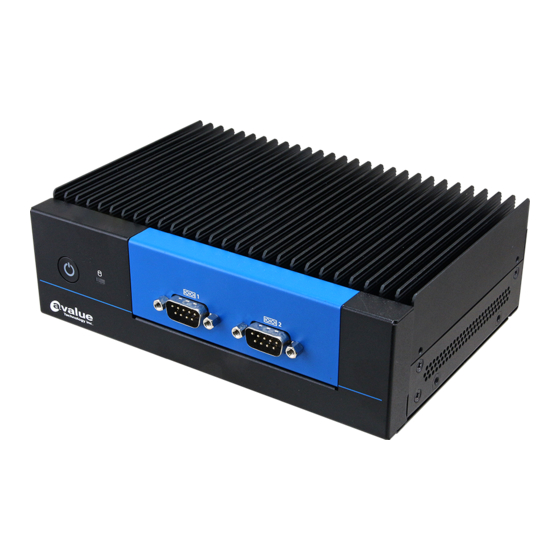
Page 10: System Overview
Power on button Serial port 1/2 connector COM1/2 1.4.2 Rear View Connectors Label Function Note HDD indicator System power indicator LAN1/2 RJ-45 Ethernet x 2 USB3.1 USB 3.1 connector x 4 USB2.0 USB 2.0 connector x 2 10 EPC-TGU-B1 Quick Reference Guide... - Page 11 Quick Reference Guide DC-IN DC Power-in connector DP1/2 DP connector x 2 Audio Audio connector Mic-In + Line-Out EPC-TGU-B1 Quick Reference Guide 11...
-
Page 12: System Dimensions
EPC-TGU-B1 1.5 System Dimensions 1.5.1 Front & Top View (Unit: mm) 12 EPC-TGU-B1 Quick Reference Guide... -
Page 13: Hardware Configuration
Quick Reference Guide 2. Hardware Configuration For advanced information, please refer to: 1- EPC-TGU-B1 User’s Manual Note: If you need more information, please visit our website: http://www.avalue.com.tw EPC-TGU-B1 Quick Reference Guide 13... -
Page 14: Epc-Tgu-B1 Connector Mapping
2.1 EPC-TGU-B1 connector mapping 2.1.1 Serial port 1/2 connector (COM1/2) RS-232 Signal PIN PIN Signal DCD# DSR# RTS# CTS# RS-485 DTR# Signal PIN PIN Signal 485_Tx- 485_Tx+ RS-422 Signal PIN PIN Signal 422_Tx- 422_Tx+ 422_Rx+ 422_Rx- 14 EPC-TGU-B1 Quick Reference Guide... -
Page 15: Installing Hard Disk & Memory (Epc-Tgu-B1)
Quick Reference Guide 2.2 Installing Hard Disk & Memory (EPC-TGU-B1) Step1. For HDD installation, remove four M3*5L screws from bottom cover. Step2. Install HDD. Step3. Fix HDD with four M3*4 screws. EPC-TGU-B1 Quick Reference Guide 15... - Page 16 EPC-TGU-B1 Step4. Put the bottom back and fix with four M3*5 screws. Step5. Slide the DDR4 SODIMM into the memory socket and press it down until properly seated. 16 EPC-TGU-B1 Quick Reference Guide...
-
Page 17: Installing M.2 B-Key (2242)/ (3042) Card (Epc-Tgu-B1)
Quick Reference Guide 2.3 Installing M.2 B-Key (2242)/ (3042) card (EPC-TGU-B1) Step1.Fix bracket (16.6*22) and standoff screw with M3*4 screw. Step2.Insert M.2 B-Key (2242)/ (3042) card into designated locations and fasten with M2*3 screw to complete installation. EPC-TGU-B1 Quick Reference Guide 17... -
Page 18: Installing M.2 E-Key Card (Epc-Tgu-B1)
EPC-TGU-B1 2.4 Installing M.2 E-Key card (EPC-TGU-B1) Step1. Insert M.2 E-Key card into designated locations and fasten with M3*4 screw to complete installation. 18 EPC-TGU-B1 Quick Reference Guide... -
Page 19: Installing M.2 M-Key (2242) Card (Epc-Tgu-B1)
Quick Reference Guide 2.5 Installing M.2 M-Key (2242) card (EPC-TGU-B1) Step1. Fix bracket (24.6*22*3) and standoff screw with M3*4 screw. Step2. Insert M.2 M-Key (2242) card into designated locations and connect the bracket (24.6*22*3) with M2*3 screws to complete installation. -
Page 20: Installing Mounting Brackets (Epc-Tgu-B1)
EPC-TGU-B1 2.6 Installing Mounting Brackets (EPC-TGU-B1) Step1. Fasten four M3*5 screws on each side of the system to secure Mounting brackets. 20 EPC-TGU-B1 Quick Reference Guide... -
Page 21: Bios Setup
Quick Reference Guide 3.BIOS Setup EPC-TGU-B1 Quick Reference Guide 21... -
Page 22: Introduction
If the message disappears before you respond and you still wish to enter Setup, restart the system to try again by turning it OFF then ON or pressing the "RESET" button on the system case. You may also restart by simultaneously pressing <Ctrl>, <Alt>, and <Delete> keys. 22 EPC-TGU-B1 Quick Reference Guide... -
Page 23: Using Setup
Note: Some of the navigation keys differ from one screen to another. To Display a Sub Menu Use the arrow keys to move the cursor to the sub menu you want. Then press <Enter>. A “” pointer marks all sub menus. EPC-TGU-B1 Quick Reference Guide 23... -
Page 24: Getting Help
BIOS Vendor and your systems manufacturer to provide the absolute maximum performance and reliability. Even a seemingly small change to the chipset setup has the potential for causing you to use the override. 24 EPC-TGU-B1 Quick Reference Guide... -
Page 25: Bios Setup
<Enter> to accept and enter the sub-menu. 3.6.1 Main Menu This section allows you to record some basic hardware configurations in your computer and set the system clock. EPC-TGU-B1 Quick Reference Guide 25... -
Page 26: System Language
Visit the Avalue website (www.avalue.com.tw) to download the latest product and BIOS information. 3.6.2 Advanced Menu This section allows you to configure your CPU and other system devices for basic operation through the following sub-menus. 26 EPC-TGU-B1 Quick Reference Guide... -
Page 27: Connectivity Configuration
Otherwise Disable Integrated CNVi Mode Integrated solution (CNVi) will be enabled; [Disable Auto Detection[Default] Integrated] disables Integrated Solution. NOTE: When CNVi is present, the GPIO pins that are used for radio. EPC-TGU-B1 Quick Reference Guide 27... -
Page 28: Cpu Configuration
Options Description When enabled, a VMM can utilize the additional Intel (VMX) Virtualization Disabled hardware capabilities provided by Vanderpool Technology Enabled[Default] Technology. All[Default] Number of cores to enable in each processor Active Processor Cores package. 28 EPC-TGU-B1 Quick Reference Guide... -
Page 29: Power & Performance
Allows more than two frequency ranges to be Intel® SpeedStep™ Enabled[Default], supported. Eanble/Disable Intel® Speed Shift Technology Intel® Speed Shift Disabled support. Enabling will expose the CPPC v2 interface to Technology Enabled[Default], allow for hardware controlled P-states. EPC-TGU-B1 Quick Reference Guide 29... -
Page 30: Pch-Fw Configuration
Enable/Disable C1E. When enabled, CPU will switch Enhanced C-States Enabled[Default], to minimum speed when all cores enter C-State. 3.6.2.4 PCH-FW Configuration Item Option Description Disabled When Disabled ME will be put into ME Temporarily ME State Enabled[Default], Disabled More. 30 EPC-TGU-B1 Quick Reference Guide... -
Page 31: Firmware Update Configuration
Quick Reference Guide 3.6.2.4.1 Firmware Update Configuration Item Option Description Disabled[Default], ME FW Image Re-Flash Enable/Disable Me FW Image Re-Flash function. Enabled 3.6.2.5 Trusted Computing EPC-TGU-B1 Quick Reference Guide 31... -
Page 32: Acpi Settings
(OS/S4 Sleep State). This option may not be Enabled[Default], effective with some operating systems. Suspend Disabled, Select the highest ACPI sleep state the system will ACPI Sleep State S3 (Suspend to RAM)[Default] enter when the SUSPEND button is pressed. 32 EPC-TGU-B1 Quick Reference Guide... -
Page 33: Super Io Configuration
3.6.2.7.1 ~ 3.6.2.7.2 for more information. Item Description Serial Port 1 Configuration Set Parameters of Serial Port 1 (COMA). Serial Port 2 Configuration Set Parameters of Serial Port 2 (COMB). 3.6.2.7.1 Serial Port 1 Configuration EPC-TGU-B1 Quick Reference Guide 33... -
Page 34: Serial Port 2 Configuration
UART 485 3.6.2.7.2 Serial Port 2 Configuration Item Option Description Disabled Serial Port Enable or Disable Serial Port (COM). Enabled[Default], UART 232[Default] UART 232 422 485 UART 422 Change the Serial Port as RS232/422/485. UART 485 34 EPC-TGU-B1 Quick Reference Guide... -
Page 35: S5 Rtc Wake Settings
Fixed Time, system will wake on the hr::min::sec specified. Wake system from S5 Fixed Time Select Dynamic Time, System will wake on the current time Dynamic Time + Increase minute(s). 3.6.2.9 Serial Port Console Redirection EPC-TGU-B1 Quick Reference Guide 35... -
Page 36: Legacy Console Redirection Settings
Console Redirection EMS Console Redirection Enable or Disable. Enabled 3.6.2.9.1 Legacy Console Redirection Settings Item Option Description Select a COM port to display redirection of Legacy Redirection COM Port COM0 OS and Legacy OPROM Messages. 36 EPC-TGU-B1 Quick Reference Guide... -
Page 37: Usb Configuration
Auto[Default] Floppy enumerates devices according to their media format. Optical drives are emulated as ‘CDROM’, Mass Storage Devices Forced FDD Hard Disk drives with no media will be emulated according to a CD-ROM drive type. EPC-TGU-B1 Quick Reference Guide 37... -
Page 38: Network Stack Configuration
EPC-TGU-B1 3.6.2.11 Network Stack Configuration Item Options Description Disabled[Default] Network Stack Enable/Disable UEFI Network Stack. Enabled 3.6.2.12 NVMe Configuration 38 EPC-TGU-B1 Quick Reference Guide... -
Page 39: Chipset
Quick Reference Guide 3.6.3 Chipset 3.6.3.1 System Agent (SA) Configuration Item Option Description Disabled VT-d VT-d capability. Enabled[Default] EPC-TGU-B1 Quick Reference Guide 39... -
Page 40: Memory Configuration
EPC-TGU-B1 3.6.3.1.1 Memory Configuration 3.6.3.1.2 Graphics Configuration Item Option Description Select which of IGFX/PEG/PCI Graphics device should Primary Display Auto IGFX[Default] be Primary Display Or select HG for Hybrid Gfx. 40 EPC-TGU-B1 Quick Reference Guide... -
Page 41: Vmd Setup Menu
Enable/Disable VMD controller Enabled Note: RAID/RST Mode support RAID 0 & RAID 1. To set RAID configuration, please follow the instruction below. EPC-TGU-B1 Quick Reference Guide 41... - Page 42 Step 1: Enter “VMD Configuration” Enable “Enable VMD controller” Select “Save Changes and Reset” to reboot system Step 2: After enabled “Enable VMD controller”, will show submenu “Intel(R) Rapid Storage Technology”, please enter it for RAID configuration. 42 EPC-TGU-B1 Quick Reference Guide...
- Page 43 Quick Reference Guide Step 3: Enter “Create RAID Volume” Step 4: - Enter “Name” for the name of raid - Set “RAID Level” as “RAID0 (Stripe)” EPC-TGU-B1 Quick Reference Guide 43...
- Page 44 EPC-TGU-B1 Step 5: - Select disk SATA 0.0 and SATA 0.1 - Enter “Create Volume” Step 6: Completed. This page shows the information of raid created by user 44 EPC-TGU-B1 Quick Reference Guide...
- Page 45 Quick Reference Guide Delete Raid 0: Step1: Enter “Delete” Step 2: Select “Yes“ to delete RAID EPC-TGU-B1 Quick Reference Guide 45...
- Page 46 Set RAID 1 (DATA Mirroring) Step1: Enter “Create RAID Volume” Step2: - Enter “Name” for the name of raid - Set “RAID Level “ as “RAID1 (Mirror)” - Select disk “SATA 0.0” and ”SATA 0.1” - Enter “Create Volume” 46 EPC-TGU-B1 Quick Reference Guide...
- Page 47 Quick Reference Guide Step 3: Raid 1 be created. Select ”Volume1” to see detail. Step 4: Completed. This page show the information of raid created by user. EPC-TGU-B1 Quick Reference Guide 47...
- Page 48 EPC-TGU-B1 Delete Raid 1 Step1: Enter “Delete” Step2: Select “Yes” to delete RAID 48 EPC-TGU-B1 Quick Reference Guide...
-
Page 49: Pch-Io Configuration
Quick Reference Guide 3.6.3.2 PCH-IO Configuration 3.6.3.2.1 PCI Express Configuration EPC-TGU-B1 Quick Reference Guide 49... -
Page 50: Pci Express Root Port 6(M.2 Keye)
L0s State AUTO – BIOS auto configure ASPM DISABLE – Disables ASPM. L0sL1 Auto Disabled, L1 Substates L1.1 PCI Express L1 Substates settings. L1.1 & L1.2[Default] Auto[Default] Gen1 PCIe Speed Configure PCIe Speed. Gen2 Gen3 50 EPC-TGU-B1 Quick Reference Guide... -
Page 51: Pci Express Root Port 7(Lan2-I225/I226)
L0s State AUTO – BIOS auto configure ASPM DISABLE – Disables ASPM. L0sL1 Auto Disabled, L1 Substates L1.1 PCI Express L1 Substates settings. L1.1 & L1.2[Default] Auto[Default] Gen1 PCIe Speed Configure PCIe Speed. Gen2 Gen3 EPC-TGU-B1 Quick Reference Guide 51... -
Page 52: Pci Express Root Port 8(Lan3-I225/I226)
L0s State AUTO – BIOS auto configure ASPM DISABLE – Disables ASPM. L0sL1 Auto Disabled, L1 Substates L1.1 PCI Express L1 Substates settings. L1.1 & L1.2[Default] Auto[Default] Gen1 PCIe Speed Configure PCIe Speed. Gen2 Gen3 52 EPC-TGU-B1 Quick Reference Guide... -
Page 53: Pci Express Root Port 12(M.2 Keyb)
L0s State AUTO – BIOS auto configure ASPM DISABLE – Disables ASPM. L0sL1 Auto Disabled, L1 Substates L1.1 PCI Express L1 Substates settings. L1.1 & L1.2[Default] Auto[Default] Gen1 PCIe Speed Configure PCIe Speed. Gen2 Gen3 EPC-TGU-B1 Quick Reference Guide 53... -
Page 54: Sata And Rst Configuration
EPC-TGU-B1 3.6.3.2.2 SATA And RST Configuration Item Options Description Enabled[Default] SATA Controller(s) Enable/Disable SATA Device Disabled, Disabled Port 0 Enable or Disable SATA Port Enabled[Default] Disabled Port 1 Enable or Disable SATA Port Enabled[Default] 54 EPC-TGU-B1 Quick Reference Guide... -
Page 55: Hd Audio Configuration
3.6.3.2.3 HD Audio Configuration Item Option Description Control Detection of the HD-Audio device. Disabled HD Audio Disable = HDA will be unconditionally disabled Enabled[Default] Enabled = HDA will be unconditionally enabled. 3.6.3.3 Board & Panel Configuration EPC-TGU-B1 Quick Reference Guide 55... -
Page 56: Show Dmi Info
1 min 2 min 10 min 30 min USB Standby Disabled Enable/Disabled USB12, USB34 Standby Power Power(Rear) Enabled[Default] during S3/S4/S5. USB Standby Disabled Enable/Disabled USB56, USB67 Standby Power Power(Internal) Enabled[Default] during S3/S4/S5. 3.6.3.3.1 SHOW DMI INFO 56 EPC-TGU-B1 Quick Reference Guide... -
Page 57: Security
Quick Reference Guide 3.6.4 Security Administrator Password Set setup Administrator Password User Password Set User Password EPC-TGU-B1 Quick Reference Guide 57... -
Page 58: Secure Boot
Platform Key(PK) is enrolled and the System is in Enabled User mode. The mode change requires platform reset. Secure Boot mode selector: Standard/Custom. In Standard Secure Boot Mode Custom mode Secure Boot Variables can be Custom[Default] configured without authentication. 58 EPC-TGU-B1 Quick Reference Guide... -
Page 59: Key Management
Quick Reference Guide 3.6.4.1.1 Key Management Item Option Description Factory Key Disabled[Default] Install factory default Secure Boot keys after the Provision Enabled platform reset and while the System is in Setup mode. 3.6.5 Boot EPC-TGU-B1 Quick Reference Guide 59... -
Page 60: Save And Exit
Enables or disables boot with initialization of a Disabled[Default] Fast Boot minimal set of devices required to launch active boot Enabled option. Has no effect for BBS boot optios. Boot Option #1/2 Set the system boot order. 3.6.6 Save and exit 60 EPC-TGU-B1 Quick Reference Guide... -
Page 61: Save Changes And Reset
This option restores all BIOS settings to the factory default. This option is useful if the controller exhibits unpredictable behavior due to an incorrect or inappropriate BIOS setting. 3.6.6.4 Launch EFI Shell from filesystem device Attempts to Launch EFI Shell application (Shellx64.efi) from one of the available filesystem devices. EPC-TGU-B1 Quick Reference Guide 61...
Need help?
Do you have a question about the EPC-TGU-B1 and is the answer not in the manual?
Questions and answers