
Related Manuals for Avalue Technology ECM-BYT2


Summary of Contents for Avalue Technology ECM-BYT2
- Page 1 ECM-BYT2 Intel® Celeron®/Atom™ SoC Processors 3.5” Micro Module User’s manual Ed – 12 November 2014 Part No. E2047392201R...
- Page 2 Disclaimer Avalue Technology Inc. reserves the right to make changes, without notice, to any product, including circuits and/or software described or contained in this manual in order to improve design and/or performance. Avalue Technology assumes no responsibility or liability for the...
-
Page 3: Technical Support
ECM-BYT2 User’s Manual otherwise specified. Applications that are described in this manual are for illustration purposes only. Avalue Technology Inc. makes no representation or warranty that such application will be suitable for the specified use without further testing or modification. -
Page 4: Product Warranty
A product returned without proof of the purchase date is not eligible for warranty service. Write the RMA number visibly on the outside of the package and ship it prepaid to your dealer. 4 ECM-BYT2 User’s Manual... -
Page 5: Table Of Contents
Miscellaneous setting connector (JFP1) ..........28 2.4.17 BIOS SPI connector (BIOS_SPI1) ............29 2.4.18 LCD backlight brightness adjustment (JBLK_CTRL1) ......29 2.4.19 EC Debug connector (JEC_ROM1)............30 2.4.20 LVDS connector (JLVDS1) ..............30 2.4.21 Power connector (PWR1) ..............31 ECM-BYT2 User’s Manual 5... - Page 6 IGD - LCD Control ..............52 3.6.3.2 South Bridge ................53 3.6.3.2.1 Azalia HD Audio ..............54 3.6.3.2.2 USB Configuration ..............54 3.6.3.2.3 PCI Express Configuration ............55 3.6.4 Security ....................56 3.6.4.1 Secure Boot menu ..............56 6 ECM-BYT2 User’s Manual...
- Page 7 Install MBI Driver ..................63 Install TXE Driver ..................64 Install VGA Driver ..................65 Install Audio Driver (For Realtek ALC892)............ 66 Install Ethernet Driver (For Realtek RTL8111E) ........... 67 Install Hub Driver ..................68 5. Mechanical Drawing ....................69 ECM-BYT2 User’s Manual 7...
-
Page 8: Getting Started
1.2 Packing List Before you begin installing your single board, please make sure that the following materials have been shipped: 1 x 3.5” ECM-BYT2 Micro Module 1 x DVD-ROM contains the followings: ... -
Page 9: Document Amendment History
ECM-BYT2 User’s Manual 1.3 Document Amendment History Revision Date Comment August 2014 Initial Release November 2014 Remove PWR_SB1 connector ECM-BYT2 User’s Manual 9... -
Page 10: Manual Objectives
We strongly recommend that you study this manual carefully before attempting to interface with ECM-BYT2 series or change the standard configurations. Whilst all the necessary information is available in this manual we would recommend that unless you are confident, you contact your supplier for guidance. -
Page 11: System Specifications
Multiple Display CRT + HDMI HDMI HDMI x 1 LCD Interface Dual channel 18/24-bit LVDS Audio AC97 Codec Realtek ALC892 Supports 5.1-CH Audio Ethernet LAN Chip 2 x Realtek RTL 8111E Ethernet Interface 10/100/1000 Base-Tx compatible ECM-BYT2 User’s Manual 11... - Page 12 Power Type AT / ATX Operating Temp. 0°C ~ 60°C Storage Temp. -40°C ~75°C Operating Humidity 0% ~ 90% relative humidity, non-condensing 5.7” x 4” (146mm x 101mm) Size (L x W) Weight 0.41 lbs (0.18 Kg) 12 ECM-BYT2 User’s Manual...
-
Page 13: Architecture Overview - Block Diagram
ECM-BYT2 User’s Manual 1.6 Architecture Overview – Block Diagram The following block diagram shows the architecture and main components of ECM-BYT2. ECM-BYT2 User’s Manual 13... -
Page 14: Hardware Configuration
ECM-BYT2 User’s Manual 2. Hardware Configuration 14 ECM-BYT2 User’s Manual... -
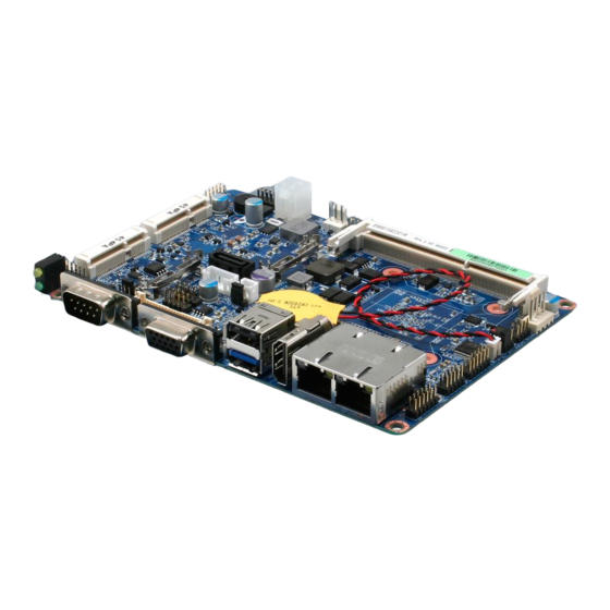
Page 15: Product Overview
ECM-BYT2 User’s Manual 2.1 Product Overview ECM-BYT2 User’s Manual 15... -
Page 16: Installation Procedure
Note: Make sure the heat sink and the CPU top surface are in total contact to avoid CPU overheating problem that would cause the system to hang or unstable 16 ECM-BYT2 User’s Manual... -
Page 17: Main Memory
ECM-BYT2 User’s Manual 2.2.1 Main Memory ECM-BYT2 provides one 204-pin DDR3L SODIMM socket, supports up to 8GB DDR3L 1066/1333 SDRAM. SODIMM Make sure to unplug the power supply before adding or removing SODIMMs or other system components. Failure to do so may cause severe damage to both the board and the components. - Page 18 (2) Static electricity can damage the electronic components of the computer or optional boards. Before starting these procedures, ensure that you are discharged of static electricity by touching a grounded metal object briefly. 18 ECM-BYT2 User’s Manual...
-
Page 19: Jumper And Connector List
Label Function Note Battery connector 2 x 1 wafer, pitch 1.25 mm CPU fan connector 4 x 1 wafer, pitch 2.54 mm CPU_FAN1 HDMI connector HDMI1 Audio connector 6 x 2 header, pitch 2.00 mm JAUDIO1 ECM-BYT2 User’s Manual 19... - Page 20 2 x 1 wafer, pitch 2.00 mm SATA1 Serial ATA connector 1 VGA1 VGA connector D-sub 15-pin, female BIOS_SPI1 BIOS SPI connector 4 x 2 header, pitch 2.00 mm M_PCIE1/2 Mini-PCI connector 1/2 SO_DIMM1 DDR3L SODIMM connector 20 ECM-BYT2 User’s Manual...
-
Page 21: Setting Jumpers & Connectors
ECM-BYT2 User’s Manual 2.4 Setting Jumpers & Connectors 2.4.1 Clear CMOS (JBAT1) Protect* Clear CMOS * Default 2.4.2 COM 1 pin 9 signal select (JRI1) Ring* +12V * Default ECM-BYT2 User’s Manual 21... -
Page 22: At/Atx Power On Type Select (Jat1)
ECM-BYT2 User’s Manual 2.4.3 AT/ATX power on type select (JAT1) * Default 2.4.4 LCD backlight brightness adjustment (JBKL_SEL1) PWM Mode* DC Mode * Default 22 ECM-BYT2 User’s Manual... -
Page 23: Battery Connector (Bt1)
ECM-BYT2 User’s Manual 2.4.5 Battery connector (BT1) Signal +3.3VSB 2.4.6 Low pin count connector (JLPC1) Signal Signal LPC_AD0 +3.3V LPC_AD1 LPC_PORT80_RST# LPC_AD2 LPC_FRAME# LPC_AD3 LPC_PORT80_CLK LPC_SERIRQ ECM-BYT2 User’s Manual 23... -
Page 24: Cpu Fan Connector (Cpu_Fan1)
FAN_PWM0 2.4.8 LCD inverter connector (JBKL1) Signal VBRIGHT BKLEN +12V 2.4.8.1 Signal Description – LCD Inverter Connector (JBKL1) Signal Signal Description Vadj = 0.75V ~ 4.25V (Recommended: 4.7KΩ, >1/16W) VBRIGHT BKLEN LCD backlight ON/OFF control signal 24 ECM-BYT2 User’s Manual... -
Page 25: On-Board Header For Usb2.0 (Jusb34)
ECM-BYT2 User’s Manual 2.4.9 On-board header for USB2.0 (JUSB34) Signal PIN PIN Signal USBVCC3 USB_DN_R_3 USB_DP_R_3 USB_Touch_R_DP USB_Touch_R_DN USBVCC3 2.4.10 On-board header for USB2.0 (JUSB56) Signal Signal USBVCC4 USB_HUB2_DN_R_1 USB_HUB2_DP_R_1 USB_HUB2_DP_R_2 USB_HUB2_DN_R_2 USBVCC4 ECM-BYT2 User’s Manual 25... -
Page 26: On-Board Header For Usb2.0 (Jusb78)
ECM-BYT2 User’s Manual 2.4.11 On-board header for USB2.0 (JUSB78) Signal Signal USBVCC5 USB_HUB2_DN_R_3 USB_HUB2_DP_R_3 USB_HUB2_DP_R_4 USB_HUB2_DN_R_4 USBVCC5 2.4.12 Serial port 1 connector (COM1) Signal PIN PIN Signal NDCDA# NDSRA# NRXDA RTSA# NTXDA NCTSA# NDTRA# NRIA# 26 ECM-BYT2 User’s Manual... -
Page 27: Serial Port 2 Connector (Jcom2)
ECM-BYT2 User’s Manual 2.4.13 Serial port 2 connector (JCOM2) Signal PIN PIN Signal NDCDB# NRXDB NTXDB NDTRB# NDSRB# NRTSB# NCTSB# NRIB# 2.4.14 Serial port 1 in RS-422/485 mode (J422_485) Signal PIN PIN Signal 485TX2- 485RX2- 485TX2+ 485RX2+ ECM-BYT2 User’s Manual 27... -
Page 28: General Purpose I/O Connector (Jdio1)
ECM-BYT2 User’s Manual 2.4.15 General purpose I/O connector (JDIO1) Signal PIN PIN Signal DIO_GP20 DIO_GP10 DIO_GP21 DIO_GP11 DIO_GP22 DIO_GP12 DIO_GP23 DIO_GP13 SMB_CLK_9555 10 SMB_DATA_9555 2.4.16 Miscellaneous setting connector (JFP1) Signal PWBT RST# PWR-LED+ PWR-LED- HDD-LED- HDD-LED+ CASE_OPEN# 28 ECM-BYT2 User’s Manual... -
Page 29: Bios Spi Connector (Bios_Spi1)
PIN PIN Signal +VSPI_BIOS SPI_ROM_CS# SPI_ROM_CLK SPI_ROM_MISO_R SPI_ROM_MOSI SPI_HOLD# 2.4.18 LCD backlight brightness adjustment (JBLK_CTRL1) Signal Note BLK_VR_MOD VR must select 10K/1% Low pulse button for BLK_BRI_UP backlight brighter Low pulse button for BLK_BRI_DN backlight dim ECM-BYT2 User’s Manual 29... -
Page 30: Ec Debug Connector (Jec_Rom1)
2.4.19 EC Debug connector (JEC_ROM1) Signal EC_SMCLK_DEBUG EC_SMDAT_DEBUG 2.4.20 LVDS connector (JLVDS1) Signal PIN PIN Signal +3.3V +3.3V LVDS_DATA0_P LVDS_DATA1_P LVDS_DATA0_N LVDS_DATA1_N LVDS_DATA2_P LVDS_DATA3_P LVDS_DATA2_N LVDS_DATA3_N LVDS_DATA4_P LVDS_DATA5_P LVDS_DATA4_N LVDS_DATA5_N LVDS_DATA6_P LVDS_DATA7_P LVDS_DATA6_N LVDS_DATA7_N LVDS_CLK1_P LVDS_CLK2_P LVDS_CLK1_N LVDS_CLK2_N +12V +12V 30 ECM-BYT2 User’s Manual... -
Page 31: Power Connector (Pwr1)
ECM-BYT2 User’s Manual 2.4.21 Power connector (PWR1) Signal PIN PIN Signal VIN_IN VIN_IN 2.4.22 SATA power connector (SATA_PWR1) Signal ECM-BYT2 User’s Manual 31... -
Page 32: Audio Connector (Jaudio1)
HD_AGND HD_AGND LINE1-R-IN LINE1-L-IN MIC1-R-IN MIC1-L-IN FRONT-JD LINE1-JD MIC1-JD HD_AGND 2.4.23.1 Signal Description – Audio connector (JAUDIO1) Signal Signal Description LINE1_JD AUDIO IN (LINE_RIN/LIN)sense pin FRONT_JD AUDIO Out(ROUT/LOUT) sense pin MIC1_JD MIC IN (MIC_RIN/LIN) sense pin 32 ECM-BYT2 User’s Manual... -
Page 33: Bios Setup
ECM-BYT2 User’s Manual 3. BIOS Setup ECM-BYT2 User’s Manual 33... -
Page 34: Introduction
If you do not press the keys at the correct time and the system does not boot, an error message will be displayed and you will again be asked to. Press F1 to Continue, DEL to enter SETUP 34 ECM-BYT2 User’s Manual... -
Page 35: Using Setup
Note: Some of the navigation keys differ from one screen to another. To Display a Sub Menu Use the arrow keys to move the cursor to the sub menu you want. Then press <Enter>. A “” pointer marks all sub menus. ECM-BYT2 User’s Manual 35... -
Page 36: Getting Help
BIOS Vendor and your systems manufacturer to provide the absolute maximum performance and reliability. Even a seemingly small change to the chipset setup has the potential for causing you to use the override. 36 ECM-BYT2 User’s Manual... -
Page 37: Bios Setup
Note: The BIOS setup screens shown in this chapter are for reference purposes only, and may not exactly match what you see on your screen. Visit the Avalue website (www.avalue.com.tw) to download the latest product and BIOS information. ECM-BYT2 User’s Manual 37... -
Page 38: Advanced Menu
This section allows you to configure your CPU and other system devices for basic operation through the following sub-menus. 3.6.2.1 ACPI Settings Item Options Description Enable ACPI Auto Disabled[Default], Enables or Disables BIOS ACPI Auto Configuration Enabled Configuration. 38 ECM-BYT2 User’s Manual... -
Page 39: It8528 Super Io Configuration
You can use this item to set up or change the IT8528 Super IO configuration for serial ports. Please refer to 3.6.2.2.1 and 3.6.2.2.2 for more information. Item Description Serial Port 1 Configuration Set Parameters of Serial Port 1 (COMA). Serial Port 2 Configuration Set Parameters of Serial Port 2 (COMB). ECM-BYT2 User’s Manual 39... -
Page 40: Serial Port 1 Configuration
IO=3F8h; IRQ=3,4,5,6,7,9,10,11,12; Select an optimal setting for Change Settings IO=2F8h; IRQ=3,4,5,6,7,9,10,11,12; Super IO Device. IO=3E8h; IRQ=3,4,5,6,7,9,10,11,12; IO=2E8h; IRQ=3,4,5,6,7,9,10,11,12; UART 232[Default], Change the Serial Port as UART 232 422 485 UART 422, RS232/ 422/ 485 UART 485 40 ECM-BYT2 User’s Manual... -
Page 41: Serial Port 2 Configuration
Option Description Enabled[Default], Enable or Disable Serial Port Serial Port Disabled (COM). Auto[Default] IO=2F8h; IRQ=3; IO=3F8h; IRQ=3,4,5,6,7,9,10,11,12; Select an optimal setting for Change Settings IO=2F8h; IRQ=3,4,5,6,7,9,10,11,12; super IO Device. IO=3E8h; IRQ=3,4,5,6,7,9,10,11,12; IO=2E8h; IRQ=3,4,5,6,7,9,10,11,12; 3.6.2.3 H/W Monitor ECM-BYT2 User’s Manual 41... -
Page 42: S5 Rtc Wake Settings
Enable or disable System wake on alarm Disabled[Default], event. Select Fixed Time, system will wake on Wake system from S5 Fixed Time the hr::min::sec specified. Select Dynamic Dynamic Time Time, System will wake on the current time + Increase minute(s). 42 ECM-BYT2 User’s Manual... -
Page 43: Serial Port Console Redirection
ECM-BYT2 User’s Manual 3.6.2.5 Serial Port Console Redirection Item Options Description Disabled[Default], Console Redirection Console Redirection Enable or Disable. Enabled 3.6.2.6 CPU Configuration Use the CPU configuration menu to view detailed CPU specification and configure the CPU. ECM-BYT2 User’s Manual 43... -
Page 44: Ppm Configuration
Enable the power management features. Custom 3.6.2.7 PPM Configuration Item Options Description Disabled, CPU C state Report Enable/Disable CPU C state report to OS. Enabled[Default] This option controls Max C state that the Max CPU C-state C1/C6/C7[Default] processor will support. 44 ECM-BYT2 User’s Manual... -
Page 45: Ide Configuration
SATA Speed Support Gen1 or Gen2. Gen2[Default] Port0 ODD SATA ODD Port Port1 ODD SATA ODD is Port0 or Port1. No ODD[Default] IDE Mode SATA Mode Select IDE/AHCI. AHCI Mode[Default] Enabled[Default] Serial-ATA Port 0/1 Enable/Disable Serial ATA Port0/1. Disabled, ECM-BYT2 User’s Manual 45... -
Page 46: Network Stack Configuration
ECM-BYT2 User’s Manual 3.6.2.9 Network Stack Configuration Item Options Description Enabled Network Stack Enable/Disable UEFI Network Stack. Disabled[Default] 3.6.2.10 CSM Configuration Item Options Description Enabled[Default] CSM Support Enable/Disable CSM Support. Disabled, 46 ECM-BYT2 User’s Manual... -
Page 47: Trusted Computing
Controls the execution of UEFI and Legacy Video UEFI only Video OpROM. Legacy only[Default] Determines OpROM execution policy for UEFI only Other PCI devices devices other than Network, Storage, or Legacy only[Default], Video. 3.6.2.11 Trusted Computing ECM-BYT2 User’s Manual 47... -
Page 48: Usb Configuration
The XHCI ownership change Disabled should be claimed by XHCI driver. This is a workaround for OSes without EHCI Enabled EHCI Hand-off hand-off support. The EHCI ownership change Disabled[Default] should be claimed by EHCI driver. 48 ECM-BYT2 User’s Manual... -
Page 49: Security Configuration
Enable/Disable BIOS AT Code from Running. Enabled, Disabled[Default], Inter® AT Platform PBA Enable/Disable BIOS AT Code from Running. Enabled TXE OVERWRITE. NORMAL:Over Write Pin OVERWRITE as high. (TXE enabled) TXE OVERWRITE OVERWRITE:OverWrite Pin as low. (TXE NORMAL[Default] disabled). ECM-BYT2 User’s Manual 49... -
Page 50: Chipset
ECM-BYT2 User’s Manual 3.6.3 Chipset 3.6.3.1 North Bridge Item Option Description Dynamic[Default] 2 GB 2.25 GB Max TOLUD Maximum Value of TOLUD. 2.5 GB 2.75 GB 3 GB 50 ECM-BYT2 User’s Manual... -
Page 51: Intel Igd Configuration
DVMT Pre-Allocated 384M/416M/448M/ by the Internal Graphics Device. 480M/512M 128MB Select DVMT 5.0 Total Graphics DVMT Total Gfx Mem 256MB[Default] Memory size used by the Internal Graphics Device. 128MB Aperture Size Select the Aperture Size. 256MB[Default] ECM-BYT2 User’s Manual 51... -
Page 52: Igd - Lcd Control
1440x900 18/2 1600x1200 24/2 1366x768 24/1 1920x1080 24/2 1680x1050 24/2 BIOS[Default] LVDS Brightness Control Method. 1.BIOS Brightness Control Method BR Button 2.Brithtness Button 3.Variable Resistor. LVDS Back Light PWM Select LVDS back light PWM duty. 100%[Default] 52 ECM-BYT2 User’s Manual... -
Page 53: South Bridge
ECM-BYT2 User’s Manual 200[Default] LVDS Back Light PWM Select LVDS back light PWM Frequency. Frequency 3.6.3.2 South Bridge Item Option Description Disabled Enable or Disable the High High Precision Timer Enabled[Default] Precision Event Timer. ECM-BYT2 User’s Manual 53... -
Page 54: Azalia Hd Audio
Disabled = Azalia will be unconditionally Enabled[Default], Audio Controller disabled. Enabled = Azalia will be Disabled unconditionally Enabled. Auto = Azalia will be enabled if present disabled otherwise. Enabled[Default], HDMI Port B Enable/Disable HDMI Port B. Disabled 3.6.3.2.2 USB Configuration 54 ECM-BYT2 User’s Manual... -
Page 55: Pci Express Configuration
Mode of operation of xHCI controller. Disabled 3.6.3.2.3 PCI Express Configuration Item Option Description Enabled[Default], Enable or Disable the PCI Express Port PCI Express Port 0/1/2/3 Disabled 0/1/2/3 in the Chipset. Auto[Default] Speed Gen 2 Configure PCIe Port Speed. Gen 1 ECM-BYT2 User’s Manual 55... -
Page 56: Security
ECM-BYT2 User’s Manual 3.6.4 Security Administrator Password Set setup Administrator Password User Password Set User Password 3.6.4.1 Secure Boot menu 56 ECM-BYT2 User’s Manual... -
Page 57: Key Management
Secure Boot Mode Custom[Default] change Image Execution policy and manage Secure Boot Keys. 3.6.4.1.1 Key Management Item Option Description Enabled, Install Factory default Secure Boot Keys Default Key Provision Disabled[Default] when System is in Setup Mode. ECM-BYT2 User’s Manual 57... -
Page 58: Boot
Enables or disables boot with Disabled[Default] initialization of a minimal set of devices Fast Boot Enabled required to launch active boot option. Has no effect for BBS boot options. Boot Option #1/2 Set the system boot order. 58 ECM-BYT2 User’s Manual... -
Page 59: Save And Exit
Reset the system after saving the changes. 3.6.6.2 Discard Changes and Reset Any changes made to BIOS settings during this session of the BIOS setup program are discarded. The setup program then exits and reboots the controller. ECM-BYT2 User’s Manual 59... -
Page 60: Restore Defaults
This option restores all BIOS settings to the factory default. This option is useful if the controller exhibits unpredictable behavior due to an incorrect or inappropriate BIOS setting. 3.6.6.4 Launch EFI Shell from filesystem device Attempts to Launch EFI Shell application (Shellx64.efi) from one of the available filesystem devices. 60 ECM-BYT2 User’s Manual... -
Page 61: Drivers Installation
ECM-BYT2 User’s Manual 4. Drivers Installation Note: Installation procedures and screen shots in this section are for your reference and may not be exactly the same as shown on your screen. ECM-BYT2 User’s Manual 61... -
Page 62: Install Chipset Driver
Windows 8.1 operation system. If the warning message appears while the installation Step 3. Click Install. process, click Continue to go on. Step 4. Click Finish to complete setup. Step1. Click Next. Step 2. Click Accept. 62 ECM-BYT2 User’s Manual... -
Page 63: Install Mbi Driver
If the warning message Step 3. Click Next. appears while the installation process, click Continue to go on. Step1. Click Next to start installation. Step 4. Click Finish to complete setup. Step 2. Click Yes to accept license agreement. ECM-BYT2 User’s Manual 63... -
Page 64: Install Txe Driver
Step 3. Click Next to continue installation. system. If the warning message appears while the installation process, click Continue to go on. Step 4. Click Finish to complete setup. Step1. Click Next to start installation. Step 2. Click Next. 64 ECM-BYT2 User’s Manual... -
Page 65: Install Vga Driver
Step 3. Click Next. based on Windows 8.1 operation system. Step 1. Click Next to continue installation. Step 4. Click Next. Step 2. Step 5. Click Finish to complete setup. Click Yes to accept license agreement. ECM-BYT2 User’s Manual 65... -
Page 66: Install Audio Driver (For Realtek Alc892)
\Driver_Audio\Realtek\ALC892\ECM-BYT2_Audio. Note: The installation procedures and screen shots in this section are based on Windows 8.1 operation system. Step 1. Click Next to continue setup. Step 2. Click Finish to complete the setup. 66 ECM-BYT2 User’s Manual... -
Page 67: Install Ethernet Driver (For Realtek Rtl8111E)
Note: The installation procedures and screen shots in this section are based on Step 3. Click Finish to complete the Windows 8.1 operation system. setup. Step 1. Click Next to continue setup. Step 2. Click Install to proceed. ECM-BYT2 User’s Manual 67... -
Page 68: Install Hub Driver
\Utility\ECM-BYT2_Hub. Note: The installation procedures and screen shots in this section are based on Windows 8.1 operation system. Step 1. Click Install to continue setup. Step 2. Click Yes to accept license agreement. 68 ECM-BYT2 User’s Manual... -
Page 69: Mechanical Drawing
ECM-BYT2 User’s Manual 5. Mechanical Drawing ECM-BYT2 User’s Manual 69... - Page 70 ECM-BYT2 User’s Manual Unit: mm 70 ECM-BYT2 User’s Manual...
- Page 71 ECM-BYT2 User’s Manual Unit: mm ECM-BYT2 User’s Manual 71...
Need help?
Do you have a question about the ECM-BYT2 and is the answer not in the manual?
Questions and answers