Table of Contents

Related Manuals for Avalue Technology ESM-ASLC


Summary of Contents for Avalue Technology ESM-ASLC
- Page 1 ESM-ASLC COM Express Rev. 3.1 Intel Atom® x7000RE Series Processors Type 6 Compact Module User’s Manual Ed – 11 November 2024 Copyright Notice Copyright © 2024 Avalue Technology Inc., ALL RIGHTS RESERVED. Part No: E2047291400R...
-
Page 2: Document Amendment History
ESM-ASLC User’s Manual Document Amendment History Revision Date Comment November 2024 Avalue Initial Release 2 ESM-ASLC User’s Manual... -
Page 3: Declaration Of Conformity
For detailed information, please always refer to the electronic user's manual. Copyright Notice © 2024 by Avalue Technology Inc. All rights are reserved. No parts of this manual may be copied, modified, or reproduced in any form or by any means for commercial use without the prior written permission of Avalue Technology Inc. -
Page 4: A Message To The Customer
ㆍDescription of your software (operating system, version, application software, etc.) ㆍA complete description of the problem ㆍThe exact wording of any error messages To receive the latest version of the user’s manual; please visit our Web site at: www.avalue.com 4 ESM-ASLC User’s Manual... - Page 5 On the other hand, if the new product defect is resulting from incorrect configuration or erroneous use by the user instead of any problem of the hardware itself, the customer will also be requested to pay for relevant handling fees. ESM-ASLC User’s Manual...
- Page 6 Lacking detailed statement of fault steps also makes the problem hard to be identified, sometimes resulting in second-time repairs. 6 ESM-ASLC User’s Manual...
- Page 7 • Product has been altered or its label of the serial number has been torn off. • Product functionality issues resulting from improper use by the user, unauthorized dismantle or alteration, unfit operation environment, improper maintenance, accident ESM-ASLC User’s Manual...
- Page 8 If the customer demands an additional maintenance analysis report, a service fee of various level will be charged depending on the warranty status. In case the analysis result shows that the defect attributes to Avalue’s faulty design or process, the analysis fee will be exempted. 8 ESM-ASLC User’s Manual...
-
Page 9: Safety Instructions
9. Position the power cord so that people cannot step on it. Do not place anything over the power cord. 10. All cautions and warnings on the equipment should be noted. 11. If the equipment is not used for a long time, disconnect it from the power source to ESM-ASLC User’s Manual... - Page 10 The equipment has obvious signs of breakage. 14. CAUTION: Danger of explosion if battery is incorrectly replaced. Replace only with the same or equivalent type recommended by the manufacturer. 15. Equipment intended only for use in a RESTRICTED ACCESS AREA. 10 ESM-ASLC User’s Manual...
-
Page 11: Explanation Of Graphical Symbols
A NOTE provides additional information intended to avoid Note inconveniences during operation. Direct current. Alternating current Stand-by, Power on FCC Certification CE Certification Follow the national requirements for disposal of equipment. Stacking layer limit This side up ESM-ASLC User’s Manual 11... - Page 12 ESM-ASLC User’s Manual Fragile Packaging Beware of water damage, moisture-proof Carton recyclable Handle with care Follow operating instructions of consult instructions for use. 12 ESM-ASLC User’s Manual...
-
Page 13: Disposing Of Your Old Product
EXPLOSION ou une fuite de liquide ou de gaz inflammable. - UNE BATTERIE soumise à une pression d'air extrêmement basse pouvant entraî ner une EXPLOSION ou une fuite de liquide ou de gaz inflammable. ESM-ASLC User’s Manual 13... -
Page 14: Table Of Contents
4.6.1.1 System Language ........................50 4.6.1.2 System Date .......................... 50 4.6.1.3 System Time .......................... 50 4.6.2 Advanced Menu ..........................51 4.6.2.1 CPU Configuration ......................... 51 4.6.2.1.1 Efficient-core Information ....................... 52 4.6.2.2 Power & Performance ......................52 14 ESM-ASLC User’s Manual... - Page 15 Secure Boot ........................... 81 4.6.5 Boot .............................. 82 4.6.6 Save and exit ..........................82 4.6.6.1 Save Changes and Reset ...................... 83 4.6.6.2 Discard Changes and Reset ....................83 4.6.6.3 Restore Defaults ........................83 5. Mechanical Drawing ....................84 ESM-ASLC User’s Manual 15...
-
Page 16: Getting Started
1.2 Packing List Before installation, please ensure all the items listed in the following table are included in the package. Item Description Q’ty ESM-ASLC COMe Module Desiccant (5g) 16 ESM-ASLC User’s Manual... -
Page 17: Manual Objectives
We strongly recommend that you study this manual carefully before attempting to set up ESM-ASLC or change the standard configurations. Whilst all the necessary information is available in this manual, we would recommend that unless you are confident, you contact your supplier for guidance. -
Page 18: System Specifications
2 x Serial Port (Only TX/RX) 8-bit GPIO 1 x LPC eSPI 1 x eSPI (W-B 10Px1 1.0mm 90D for debug conn), test with EEV-EX16 C Bus 1 x I2C SMBus 1 x SMBus Onboard NuvoTon NPCT754AADYX supports TPM 2.0 18 ESM-ASLC User’s Manual... - Page 19 ACPI 6.0 Compliant Power Mode AT/ATX Industrial: Operating (optional, selected SKUs): -40°C ~ 80°C (-40°F ~ 176°F) Operating Temp. Air Flow: 0.5m/s Storage Temp. -40°C ~ 75°C (-40°F ~ 167°F) Operating 40°C @ 95% Relative Humidity, Non-condensing Humidity ESM-ASLC User’s Manual 19...
-
Page 20: Vibration Test
1. PSD: 0.01818G²/Hz, 3.0 Grms 2. Non Operation mode 3. Test Frequency : 5-500Hz 4. Test Axis : X,Y and Z axis 5. 30 minutes per each axis 6. IEC 60068-2-64 Test:Fh Drop Test Packing Drop 20 ESM-ASLC User’s Manual... - Page 21 Reference ISTA 2A, Method : IEC-60068-2-32 Test: Ed Drop Test 1 One corner , three edges, six faces 2 ISTA 2A, IEC-60068-2-32 Test:Ed OS Information Windows 11, 64-bit, Linux Note: Specifications are subject to change without notice. ESM-ASLC User’s Manual 21...
-
Page 22: Architecture Overview-Block Diagram
ESM-ASLC User’s Manual 1.5 Architecture Overview—Block Diagram The following block diagram shows the architecture and main components of ESM-ASLC. 22 ESM-ASLC User’s Manual... -
Page 23: Hardware Configuration
User’s Manual 2. Hardware Configuration ESM-ASLC User’s Manual 23... -
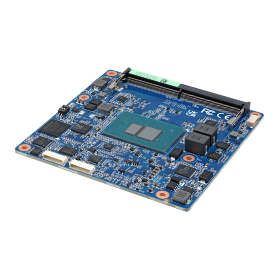
Page 24: Product Overview
ESM-ASLC User’s Manual 2.1 Product Overview 24 ESM-ASLC User’s Manual... -
Page 25: Jumper And Connector List
The following tables list the function of each of the board’s jumpers and connectors. Connectors Label Function Note BIOS_SPI1 BIOS SPI programming connector 10 x 1 wafer, pitch 1.00mm CN1A COM Express connector 1 CN1B COM Express connector 2 SODIMM1 262-pin DDR5 SDRAM DIMM socket AT/ATX mode selector ESM-ASLC User’s Manual 25... -
Page 26: Setting Jumpers & Connectors
Auto power on, no need to press Power button to enable power on/off ATX mode Press the ATX power button to enable power on/off 2.3.2 BIOS SPI programming connector (BIOS_SPI1) Signal EC_SMDAT_DBG EC_SMCLK_DBG SPI_WP# HOLD# ROM_SPI_MOSI ROM_SPI_MISO ROM_SPI_CLK ROM_CS# +3.3VSB 26 ESM-ASLC User’s Manual... -
Page 27: Com Express Connector 1 (Cn1A)
A101 B101 FAN_PWMOUT A100 B100 SER0_RX GSPI1_CLK SER0_TX GSPI1_MISO TYPE10# SPI_CS# TPM_PP SPI_MOSI SPI_CLK GPO0 SPI_MISO +3.3V_SPI PCIE_CLK_REF- PCIE_CLK_REF+ BIOS_DIS1# CB_EDP_HPD +ATX5VSB GSPI1_MOSI +ATX5VSB GPI3 +ATX5VSB LVDS_I2C_DAT/EDP_AUX- A84 +ATX5VSB LVDS_BKLT_CTRL/ LVDS_I2C_CK/EDP_AUX+ EDP_BKLT_CTRL LVDS_A_CK-/EDP_TX3- LVDS_B_CK- LVDS_A_CK+/EDP_TX3+ LVDS_B_CK+ ESM-ASLC User’s Manual 27... - Page 28 PCIE_RX2- PCIE_TX2+ A61 B61 PCIE_RX2+ A60 B60 PCIE_TX3- A59 B59 PCIE_RX3- PCIE_TX3+ A58 B58 PCIE_RX3+ A57 B57 GPO2 PCIE_TX4- A56 B56 PCIE_RX4- PCIE_TX4+ A55 B55 PCIE_RX4+ GPI0 A54 B54 GPO1 A53 B53 A52 B52 A51 B51 28 ESM-ASLC User’s Manual...
- Page 29 A33 B33 I2C_CLK HDA_BITCLK A32 B32 SPKR A31 B31 HDA_RST# A30 B30 HDA_SDIN0 HDA_SYNC A29 B29 HDA_SDIN1 (S)ATA_ACT# A28 B28 BATLOW# A27 B27 A26 B26 A25 B25 SUS_S5# A24 B24 PWR_OK A23 B23 A22 B22 A21 B21 ESM-ASLC User’s Manual 29...
- Page 30 A13 B13 SMB_SCL_S5 GBE0_MDI0- A12 B12 PWRBTN# A11 B11 LPC_CLK/ GBE0_MDI1+ A10 B10 ESPI_CK GBE0_MDI1- LPC_DRQ0#/ GBE0_LINK# ESPI_ALERT0# LPC_AD3/ GBE0_MDI2+ ESPI_IO_3 LPC_AD2/ GBE0_MDI2- ESPI_IO_2 LPC_AD1/ GBE0_LINK2500# A5 ESPI_IO_1 LPC_AD0/ GBE0_LINK1000# A4 ESPI_IO_0 LPC_FRAME#/ GBE0_MDI3+ ESPI_CS0# GBE0_MDI3- GBE0_ACT# 30 ESM-ASLC User’s Manual...
-
Page 31: Signal Description - Com Express Connector 1 (Cn1A)
PCI Express Differential Receive Pair 0-4 2.3.3.1.4 Flat Panel LVDS Signals Signal Signal Description LVDS_BKLT_CTRL Controls panel digital power. LVDS_I2C_CK I2C clock output for LVDS display use. LVDS_I2C_DAT I2C data line for LVDS display use. LVDS_VDD_EN LVDS panel power enables. ESM-ASLC User’s Manual 31... - Page 32 Signal Description SUS_S3# Indicates system is in Suspend to RAM state. Active low output. BATLOW# Indicates that external battery is low PWRBTN# Power button to bring system out of S5 (soft off), active on rising edge. 32 ESM-ASLC User’s Manual...
- Page 33 General purpose I2C port data I/O line. 2.3.3.1.11 USB3.0 Signals Signal Signal Description USB_SSTX[0:1]+ Additional transmit signal differential pairs for the SuperSpeed USB data path. USB_SSTX[0:1]- USB_SSRX[0:1]+ Additional receive signal differential pairs for the SuperSpeed USB data path. USB_SSRX[0:1]- ESM-ASLC User’s Manual 33...
-
Page 34: Com Express Connector 2 (Cn1B)
Signal Signal C110 D110 VCC_12V C109 D109 VCC_12V VCC_12V C108 D108 VCC_12V VCC_12V C107 D107 VCC_12V VCC_12V C106 D106 VCC_12V VCC_12V C105 D105 VCC_12V VCC_12V C104 D104 VCC_12V C103 D103 C102 D102 C101 D101 C100 D100 34 ESM-ASLC User’s Manual... - Page 35 RAPID_SHUTDOWN C67 D67 C66 D66 C65 D65 C64 D64 C63 D63 C62 D62 C61 D61 C60 D60 C59 D59 C58 D58 TYPE1# C57 D57 TYPE2# C56 D56 C55 D55 TYPE0# C54 D54 C53 D53 C52 D52 C51 D51 ESM-ASLC User’s Manual 35...
- Page 36 DDI1_PAIR2- DDI2_CTRLCLK_AUX+ C32 D32 DDI1_PAIR2+ C31 D31 C30 D30 DDI1_PAIR1- C29 D29 DDI1_PAIR1+ SML1_DAT C28 D28 SML1_CLK C27 D27 DDI1_PAIR0- SML0_DAT C26 D26 DDI1_PAIR0+ SML0_CLK C25 D25 DDI1_HPD C24 D24 C23 D23 C22 D22 C21 D21 36 ESM-ASLC User’s Manual...
- Page 37 C17 D17 C16 D16 DDI1_CTRLDATA_AUX- C15 D15 DDI1_CTRLCLK_AUX+ C14 D14 USB_SSRX3+ C13 D13 USB_SSTX3+ USB_SSRX3- C12 D12 USB_SSTX3- C11 D11 USB_SSRX2+ C10 D10 USB_SSTX2+ USB_SSRX2- USB_SSTX2- USB_SSRX1+ C7 USB_SSTX1+ USB_SSRX1- USB_SSTX1- USB_SSRX0+ C4 USB_SSTX0+ USB_SSRX0- USB_SSTX0- ESM-ASLC User’s Manual 37...
-
Page 38: Signal Description - Com Express Connector 2 (Cn1B)
DP AUX+function if DDI[1:2]_DDC_AUX_SEL is no connect DDI[1:2]_CTRLCLK_AUX+ HDMI/DVI 12C CTRLCLK if DDI[1:2]_DDC_AUX_SEL is pulled high DP AUX-function if DDI[1:2]_DDC_AUX_SEL is no connect DDI[1:2]_CTRLDATA_AUX- HDMI/DVI 12C CTRLDATA if DDI[1:2]_DDC_AUX_SEL is pulled high DDI[1:2]_HPD Digital Display Interface Hot-Plug Detect 38 ESM-ASLC User’s Manual... -
Page 39: Drivers Installation
Enter to find all the relevant software, utilities, and documentation. (For reference only) Note: Installation procedures and screen shots in this section are for your reference and may not be exactly the same as shown on your screen. ESM-ASLC User’s Manual 39... -
Page 40: Install Chipset Driver
If the warning message appears while the installation process, click Continue to go on. Step 3. Click Install. Step1. Click Next. Step 4. Installing. Step 2. Click Accept. Step 5. Click Finish to complete setup. 40 ESM-ASLC User’s Manual... -
Page 41: Install Vga Driver
Windows 11 operation system. Step 3. Click Repair. Step 1. Click Begin installation. Step 4. Installing. Step 2. Click I agree. Step 5. Click Finish to complete setup. ESM-ASLC User’s Manual 41... -
Page 42: Install Ethernet Driver
Note: The installation procedures and screen shots in this section are based on Windows 11 operation system. Step 3. Click Next. Step 1. Click Install Drivers and Software. Step 4. Click Next. Step 5. Click Install. Step 2. Click Next. 42 ESM-ASLC User’s Manual... - Page 43 User’s Manual Step 6. Installing. Step 7. Click Finish to complete setup. ESM-ASLC User’s Manual 43...
-
Page 44: Install Me Driver
Windows 11 operation system. Step 3. Click Next. Step 1. Click Next to continue installation. Step 4. Click Next. Step 2. Click Next. Step 5. Click Finish to complete setup. 44 ESM-ASLC User’s Manual... -
Page 45: Bios Setup
User’s Manual 4.BIOS Setup ESM-ASLC User’s Manual 45... -
Page 46: Introduction
If the message disappears before you respond and you still wish to enter Setup, restart the system to try again by turning it OFF then ON or pressing the "RESET" button on the system case. You may also restart by simultaneously pressing <Ctrl>, <Alt>, and <Delete> keys. 46 ESM-ASLC User’s Manual... -
Page 47: Using Setup
Note: Some of the navigation keys differ from one screen to another. • To Display a Sub Menu Use the arrow keys to move the cursor to the sub menu you want. Then press <Enter>. A “➢” pointer marks all sub menus. ESM-ASLC User’s Manual 47... -
Page 48: Getting Help
BIOS Vendor and your systems manufacturer to provide the absolute maximum performance and reliability. Even a seemingly small change to the chipset setup has the potential for causing you to use the override. 48 ESM-ASLC User’s Manual... -
Page 49: Bios Setup
<Enter> to accept and enter the sub-menu. 4.6.1 Main Menu This section allows you to record some basic hardware configurations in your computer and set the system clock. ESM-ASLC User’s Manual 49... -
Page 50: System Language
Note: The BIOS setup screens shown in this chapter are for reference purposes only, and may not exactly match what you see on your screen. Visit the Avalue website (www.avalue.com) to download the latest product and BIOS information. 50 ESM-ASLC User’s Manual... -
Page 51: Advanced Menu
Use the CPU configuration menu to view detailed CPU specification and configure the CPU. Item Options Description Intel (VMX) Virtualization Disabled When enabled, a VMM can utilize the additional Technology Enabled[Default] hardware capabilities provided by Vanderpool ESM-ASLC User’s Manual 51... -
Page 52: Efficient-Core Information
Number of E-cores to enable in each processor All[Default] package. Note: Number of Cores and E-cores are Active Efficient-cores looked at together. When both are {0,0}, Pcode will enable all cores. 4.6.2.1.1 Efficient-core Information 4.6.2.2 Power & Performance 52 ESM-ASLC User’s Manual... -
Page 53: Cpu - Power Management Control
Enable/Disable processor Turbo Mode (requires Turbo Mode Disabled EMTTM enabled too). AUTO means enabled. Enabled[Default], Enable/Disable CPU Power Management. Allows CPU C States Disabled to go to C states when it's not 100% utilized. 4.6.2.2.1.1 View/Configure Turbo Options ESM-ASLC User’s Manual 53... -
Page 54: Pch-Fw Configuration
Option Description Enabled[Default], When Disabled ME will be put into ME Temporarily ME State Disabled Disabled Mode. 4.6.2.3.1 Firmware Update Configuration Item Option Description Disabled[Default], ME FW Image Re-Flash Enable/Disable Me FW Image Re-Flash function. Enabled 54 ESM-ASLC User’s Manual... -
Page 55: Ptt Configuration
Selects TPM device: PTT or discrete TPM. PTT - enables PTT in SkuMgr dTPM dTPM - disables PTT is SkuMgr TPM Device Selection PTT[Default] Warning! PTT/dTPM will be disabled and all data saved on it will be lost. 4.6.2.4 Trusted Computing ESM-ASLC User’s Manual 55... -
Page 56: Apci Settings
Hibernate (OS/S4 Sleep State). This Enable Hibernation Enabled[Default], option may not be effective with some Select the highest ACPI sleep state the Suspend Disabled, ACPI Sleep State system will enter when the SUSPEND S3 (Suspend to RAM)[Default] button is pressed. 56 ESM-ASLC User’s Manual... -
Page 57: It5782 Super Io Configuration
Set Parameters of Serial Port 1 (COMA). Serial Port 2 Configuration Set Parameters of Serial Port 2 (COMB). 4.6.2.6.1 Serial Port 1 Configuration Item Option Description Enabled[Default], Serial Port Enable or Disable Serial Port (COM). Disabled ESM-ASLC User’s Manual 57... -
Page 58: Serial Port 2 Configuration
4.6.2.6.2 Serial Port 2 Configuration Item Option Description Enabled[Default], Serial Port Enable or Disable Serial Port (COM). Disabled 4.6.2.7 EC 5782 HW Monitor Item Options Description Enabled, Smart Fan Function Enables or Disables Smart Fan. Disabled[Default] 58 ESM-ASLC User’s Manual... -
Page 59: Smart Fan Mode Configuration
Description Enabled[Default] Smart Fan Function Enables or Disables Smart Fan. Disabled 4.6.2.7.1 Smart Fan Mode Configuration Item Option Description Manual Mode[Default]/Mode 01/ CPU Smart Fan Mode CPU Smart Fan Mode Select. Mode 02/Mode 03/Mode 04/Mode 05/ ESM-ASLC User’s Manual 59... -
Page 60: S5 Rtc Wake Settings
Enable or disable System wake on alarm event. Select Disabled[Default], Fixed Time, system will wake on the hr::min::sec specified. Wake system from S5 Fixed Time Select Dynamic Time, System will wake on the current time Dynamic Time + Increase minute(s). 60 ESM-ASLC User’s Manual... -
Page 61: Serial Port Console Redirection
User’s Manual 4.6.2.9 Serial Port Console Redirection Item Options Description Disabled[Default], Console Redirection Console Redirection Enable or Disable. Enabled Disabled[Default], Console Redirection EMS Console Redirection Enable or Disable. Enabled 4.6.2.9.1 COM0 ESM-ASLC User’s Manual 61... - Page 62 With this mode enabled only text will be sent. Recorder Mode Enabled This is to capture Terminal data. Disabled[Default] Enables or disables extended terminal Resolution 100x31 Enabled resolution. VT100[Default] Intel Linux XTERMR6 Putty KeyPad Select FunctionKey and KeyPad on Putty. ESCN VT400 62 ESM-ASLC User’s Manual...
-
Page 63: Console Redirection Settings
Hardware RTS/CTS be sent to stop the data flow. Once the buffers are empty, a ‘start’ signal can be sent Software Xon/Xoff to re-start the flow. Hardware flow control uses two wires to send start/stop signals. ESM-ASLC User’s Manual 63... -
Page 64: Usb Configuration
Mass storage device emulation type. ‘AUTO’ Auto[Default] Floppy enumerates devices according to their media Mass Storage Devices Forced FDD format. Optical drives are emulated as ‘CDROM’, drives with no media will be Hard Disk CD-ROM emulated according to a drive type. 64 ESM-ASLC User’s Manual... -
Page 65: Network Stack Configuration
Enable/Disable UEFI Network Stack. Disabled[Default] Item Options Description Enabled[Default] Network Stack Enable/Disable UEFI Network Stack. Disabled Enable Ipv4 PXE Boot Support. If disabled IPV4 Enabled Ipv4 PXE Support Disabled[Default] PXE boot option will not be created. ESM-ASLC User’s Manual 65... -
Page 66: Nvme Configuration
HTTP boot option will not be created. Wait time to press ESC key to abort the PXE PXE boot wait time boot. Number of times presence of media will be Media detect count checked. 4.6.2.12 NVMe Configuration 66 ESM-ASLC User’s Manual... -
Page 67: Sdio Configuration
Auto Option: Access SD device in DMA mode if controller supports ADMA SDIO Access Mode it, otherwise in PIO mode. DMA Option: Access SD device in DMA SDMA mode. PIO Option: Access SD device in PIO mode. 4.6.3 Chipset ESM-ASLC User’s Manual 67... -
Page 68: System Agent (Sa) Configuration
ESM-ASLC User’s Manual 4.6.3.1 System Agent (SA) Configuration Item Option Description Enabled[Default] VT-d VT-d capability. Disabled 4.6.3.1.1 Memory Configuration 68 ESM-ASLC User’s Manual... -
Page 69: Graphics Configuration
> 2048MB aperture. To use this feature, 1024MB please disable CSM Support. Select VBT for GOP Driver. VBT1[Default] VBTx DDIA | DDIB | TCP0. VBT Select VBT2 VBT1 eDP |DP_HDMI|DP_HDMI. VBT3 VBT2 eDP | DP | DP. VBT3 eDP | HDMI |HDMI. ESM-ASLC User’s Manual 69... -
Page 70: Pch-Io Configuration
ESM-ASLC User’s Manual 4.6.3.2 PCH-IO Configuration 4.6.3.2.1 PCI Express Configuration 70 ESM-ASLC User’s Manual... - Page 71 PCI Express L1 Substates settings. L1SS L1 Substates L1.1 cannot be enabled when CLKREQMSG is L1.1 & L1.2 disabled. Disabled[Default] Enable/Disable Precision Time Enabled Measurement. Auto[Default] Gen1 Gen2 PCIe Speed Configure PCIe Speed. Gen3 Gen4 Gen5 ESM-ASLC User’s Manual 71...
- Page 72 PCI Express L1 Substates settings. L1SS L1 Substates L1.1 cannot be enabled when CLKREQMSG is L1.1 & L1.2 disabled. Disabled[Default] Enable/Disable Precision Time Enabled Measurement. Auto[Default] Gen1 Gen2 PCIe Speed Configure PCIe Speed. Gen3 Gen4 Gen5 72 ESM-ASLC User’s Manual...
- Page 73 PCI Express L1 Substates settings. L1SS L1 Substates L1.1 cannot be enabled when CLKREQMSG is L1.1 & L1.2 disabled. Disabled[Default] Enable/Disable Precision Time Enabled Measurement. Auto[Default] Gen1 Gen2 PCIe Speed Configure PCIe Speed. Gen3 Gen4 Gen5 ESM-ASLC User’s Manual 73...
- Page 74 PCI Express L1 Substates settings. L1SS L1 Substates L1.1 cannot be enabled when CLKREQMSG is L1.1 & L1.2 disabled. Disabled[Default] Enable/Disable Precision Time Enabled Measurement. Auto[Default] Gen1 Gen2 PCIe Speed Configure PCIe Speed. Gen3 Gen4 Gen5 74 ESM-ASLC User’s Manual...
- Page 75 PCI Express L1 Substates settings. L1SS L1 Substates L1.1 cannot be enabled when CLKREQMSG is L1.1 & L1.2 disabled. Disabled[Default] Enable/Disable Precision Time Enabled Measurement. Auto[Default] Gen1 Gen2 PCIe Speed Configure PCIe Speed. Gen3 Gen4 Gen5 ESM-ASLC User’s Manual 75...
-
Page 76: Sata And Rst Configuration
ESM-ASLC User’s Manual 4.6.3.2.2 SATA Configuration Item Options Description Enabled[Default] SATA Controller(s) Enable/Disable SATA Device. Disabled Disabled[Default] Port 0/1 Enable or Disable SATA Port. Enabled 4.6.3.2.3 HD Audio Configuration 76 ESM-ASLC User’s Manual... -
Page 77: Serialio Configuration
I2C1,2,3 UART0 and UART1, SPi0,1 UART2. Enables/Disables SerialIo Controller if given device is Disabled[Default] SPI1 Controller Function 0 PSF disabling is skipped. PSF default will Enabled remain and device PCI CFG Space will still be visible. ESM-ASLC User’s Manual 77... -
Page 78: Scs Configuration
Enable or Disable SCS eMMC 5.1 HS400 Mode. Enabled[Default] Disabled[Default] Software tuning should improve eMMC HS400 Enable HS400 software tuning Enabled stability at the expense of boot time. 33 Ohm Driver Strength 40 Ohm[Default] Sets I/O driver strength. 50 Ohm 78 ESM-ASLC User’s Manual... -
Page 79: Board & Panel Configuration
1680x1050 24/2 Panel Brightness Control Method. Panel Brightness Control BIOS[Default] 1.BIOS Method OS Driver 2.OS Driver. Panel Brightness Select Panel back light PWM duty. 100%[Default] Panel Back Light PWM 200[Default] Select Panel back light PWM Frequency. Frequency ESM-ASLC User’s Manual 79... -
Page 80: Security
Watch Dog Select WatchDog. 1 min 2 min 10 min 30 min 7-bit address of SPB1002. Disabled[Default] I2C0 Test device CTB-20 Disabled(No Device) Enabled Enabled(NCT5655, 0x20) Disabled[Default] SHOW DMI INFO SHOW DMI INFO. Enabled 4.6.4 Security 80 ESM-ASLC User’s Manual... -
Page 81: Secure Boot
Enabled, Platform Key(PK) is enrolled and the Secure Boot Enabled System is in User mode. The mode chagne requires platform reset. Secure Boot mode selector: Standard/Custom. In Standard Secure Boot Mode Custom mode Secure Boot Variables can be Custom[Default] configured without authentication. ESM-ASLC User’s Manual 81... -
Page 82: Boot
65535(0xFFFF) means indefinite waiting. On[Default] Bootup NumLock State Select the Keyboard NumLock state Disabled[Default] Quiet Boot Enables or disables Quiet Boot option Enabled Boot Option #1 Set the system boot order. 4.6.6 Save and exit 82 ESM-ASLC User’s Manual... -
Page 83: Save Changes And Reset
The setup program then exits and reboots the controller. 4.6.6.3 Restore Defaults This option restores all BIOS settings to the factory default. This option is useful if the controller exhibits unpredictable behavior due to an incorrect or inappropriate BIOS setting. ESM-ASLC User’s Manual 83... -
Page 84: Mechanical Drawing
ESM-ASLC User’s Manual 5. Mechanical Drawing 84 ESM-ASLC User’s Manual... - Page 85 User’s Manual Unit: mm ESM-ASLC User’s Manual 85...
Need help?
Do you have a question about the ESM-ASLC and is the answer not in the manual?
Questions and answers