
Related Manuals for Avalue Technology ECM-LX800W Series


Summary of Contents for Avalue Technology ECM-LX800W Series
- Page 1 ECM-LX800W Series 3.5” AMD LX800 Wide Temp Micro Module User’s Manual Ed – 6 September, 2016 Part No. E2047351701R...
- Page 2 For detailed information, please always refer to the electronic user's manual. Copyright Notice Copyright 2016 Avalue Technology Inc., ALL RIGHTS RESERVED. No part of this document may be reproduced, copied, translated, or transmitted in any form or by any means, electronic or mechanical, for any purpose, without the prior written permission of the original manufacturer.
- Page 3 User’s Manual Disclaimer Avalue Technology Inc. reserves the right to make changes, without notice, to any product, including circuits and/or software described or contained in this manual in order to improve design and/or performance. Avalue Technology assumes no responsibility or liability for the...
- Page 4 In addition, free technical support is available from Avalue engineers every business day. We are always ready to give advice on application requirements or specific information on the installation and operation of any of our products. Please do not hesitate to call or e-mail 4 ECM-LX800W Series User’s Manual...
- Page 5 A product returned without proof of the purchase date is not eligible for warranty service. 5. Write the RMA number visibly on the outside of the package and ship it prepaid to your dealer. ECM-LX800W Series User’s Manual 5...
-
Page 6: Table Of Contents
Signal Description – TFT Panel Display (JTFT) ..............34 2.4.16.2 2.4.17 USB Connector 0 & 1 (JUSB1) ....................35 2.4.18 USB Connector 2 & 3 (JUSB2) ....................35 2.4.19 LCD Backlight Brightness Adjustment Connector (JVR) ............36 6 ECM-LX800W Series User’s Manual... - Page 7 3.5.4 Integrated Peripherals ........................ 54 3.5.5 IT8888 ISA Decode IO ....................... 56 3.5.6 IT8888 ISA Decode Memory...................... 57 3.5.7 Power Management Setup ......................59 3.5.7.1 ACPI Suspend Type ......................59 3.5.7.2 Power Management ......................59 ECM-LX800W Series User’s Manual 7...
- Page 8 CMOS BATTERY HAS FAILED ....................90 CMOS CHECKSUM ERROR ......................90 DISK BOOT FAILURE, INSERT SYSTEM DISK AND PRESS ENTER ........90 DISKETTE DRIVES OR TYPES MISMATCH ERROR - RUN SETUP ......... 90 DISPLAY SWITCH IS SET INCORRECTLY ................. 91 8 ECM-LX800W Series User’s Manual...
- Page 9 BIOS ROM checksum error - System halted................. 94 Memory test fail..........................94 POST Codes..........................95 40.1 Normal POST Code ....................... 95 40.2 Quick POST Codes ......................101 40.3 S4 POST Codes ........................103 40.4 BootBlock POST Codes ...................... 104 ECM-LX800W Series User’s Manual 9...
-
Page 10: Getting Started
— 1 x USB cable (10P/2.54mm-10P/2.0mm) — 1 x Bracket with serial and printer cable (2.0mm pitch) — 1 x Serial ATA cables (7-pin, standard) — 1 x PS/2 Keyboard & mouse Y cable (6-pin, Mini-DIN) 10 ECM-LX800W Series User’s Manual... -
Page 11: Document Amendment History
User’s Manual 1.3 Document Amendment History Revision Date Comment April 2011 Avalue Initial Release September 2016 Avalue Update Setting Jumpers & Connectors ECM-LX800W Series User’s Manual 11... -
Page 12: Manual Objectives
We strongly recommend that you study this manual carefully before attempting to set up ECM-LX800W series or change the standard configurations. Whilst all the necessary information is available in this manual we would recommend that unless you are confident, you contact your supplier for guidance. -
Page 13: System Specifications
TFT: 1600 x 1200 @ 16 bpp (60 Hz) CRT + LVDS Multiple Display PCI Bus VGA/LCD interface, Support 18/24-bit TFT panel VGA/LCD Interface Chipset: NS DS90C363A (18-bit); (NS DS90C385A(24-bit)) [Co-lay] LVDS Interface Support 18-bit LVDS Panel (24-bit is optional) ECM-LX800W Series User’s Manual 13... - Page 14 +5V, +12V (for inverter) Power Requirement AT/ATX Power Type -40~85°C Operating Temp. Operating Humidity 0%~90% relative humidity, non-condensing Size (L x W) 5.7" x 4" (146 mm x 101 mm) Weight 0.44 lbs (0.2 Kg) 14 ECM-LX800W Series User’s Manual...
-
Page 15: Architecture Overview-Block Diagram
User’s Manual 1.6 Architecture Overview—Block Diagram The following block diagram shows the architecture and main components of ECM-LX800W. ECM-LX800W Series User’s Manual 15... -
Page 16: Hardware Configuration
ECM-LX800W Series 2. Hardware Configuration 16 ECM-LX800W Series User’s Manual... -
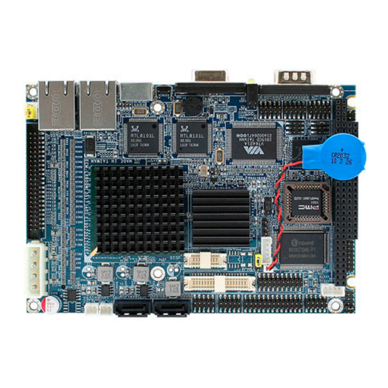
Page 17: Product Overview
User’s Manual 2.1 Product Overview ECM-LX800W Series User’s Manual 17... -
Page 18: Installation Procedure
Window must be entered and configured correctly to match the particular system configuration. 7. If TFT panel display is to be utilized, make sure the panel voltage is correctly set before connecting the display cable and turning on the power. 18 ECM-LX800W Series User’s Manual... -
Page 19: Main Memory
SDRAM SODIMM (Rear side) Make sure to unplug the power supply before adding or removing DIMMs or other system components. Failure to do so may cause severe damage to both the board and the components. ECM-LX800W Series User’s Manual 19... - Page 20 (2) Static electricity can damage the electronic components of the computer or optional boards. Before starting these procedures, ensure that you are discharged of static electricity by touching a grounded metal object briefly. 20 ECM-LX800W Series User’s Manual...
-
Page 21: Jumper And Connector List
3 x 1 header, pitch 2.54mm COM1-Ring, +5V, +12V power select 3 x 2 header, pitch 2.0mm JRI1 Front Panel Power selector 5 x 2 header, pitch 2.0mm PWR2 Power AT/ATX selector 3 x 2 header, pitch 2.54mm ECM-LX800W Series User’s Manual 21... - Page 22 2 x 2 header, pitch 2.54mm RSTBTN Reset button Button SATA_PWR1 SATA power connector 2 x 1 wafer, pitch 2.0mm SATA_PWR2 SATA power connector 2 x 1 wafer, pitch 2.0mm SODIMM 200-pin DDR SODIMM socket VGA connector D-sub 15-pin, female 22 ECM-LX800W Series User’s Manual...
-
Page 23: Setting Jumpers & Connectors
User’s Manual 2.4 Setting Jumpers & Connectors 2.4.1 Clear CMOS (JBAT) Protect* Clear CMOS * Default 2.4.2 COM1-Ring, +5V, +12V power select(JRI1) Ring* +12V * Default ECM-LX800W Series User’s Manual 23... -
Page 24: Front Panel Power Selector (Jfp)
Front Panel Power selector (JFP) Signal PWBT PWR MSEL PWR-LED HDD-LED CASE OPEN# * Default 2.4.4 AT/ATX Power selector (PWR2) Signal PSON# +5VSB Note: For ATX Connect pin 1 & 3 to power supply * Default 24 ECM-LX800W Series User’s Manual... -
Page 25: Signal Description -At/ Atx Mode & Input Power Type
1) Connect to power and set the board in AT mode. supply ATX Mode 2) Connect pin 1 & 3 to (PWR MSEL) Use ATX type power input, power supply and set the board in ATX mode. ECM-LX800W Series User’s Manual 25... -
Page 26: Sata Power Connector (Sata_Pwr1/ Sata_Pwr2)
ECM-LX800W Series 2.4.5 SATA Power connector (SATA_PWR1/ SATA_PWR2) SATA_PWR2 SATA_PWR1 Signal * Default 2.4.6 LPC connector (LPC1) Signal Signal LAD0 +3.3V LAD1 PCI_RST# LAD2 LFRAME# LAD3 ENE_PCICLK SERIRQ VCCSB * Default 26 ECM-LX800W Series User’s Manual... -
Page 27: Audio Connector (Jaudio)
User’s Manual 2.4.7 Audio Connector (JAUDIO) Signal Signal MIC-REF MIC-IN LIN_L LIN_R LINEOUT _L LINEOUT _R 2.4.8 CD-ROM audio input connector (JCDIN) Signal CD_L CD_R ECM-LX800W Series User’s Manual 27... -
Page 28: Lcd Inverter Connector (Jbkl)
LCD brightness through the VR signal controlled by JVR. Please see the JVR section for detailed circuitry information. 2.4.9.1 Signal Description – LCD Inverter Connector (JBKL) Signal Signal Description Vadj = 0.75V ~ 4.25V (Recommended: 4.7KΩ, >1/16W) ENBKL LCD backlight ON/OFF control signal 28 ECM-LX800W Series User’s Manual... -
Page 29: Serial Port 2 Connector In Rs-232 Mode (Jcom2)
User’s Manual 2.4.10 Serial port 2 connector in RS-232 Mode (JCOM2) Signal Signal 2.4.11 Serial port 2 in RS-422/485 mode (JRS422/485) In 422 mode Signal Signal In 485 mode Signal Signal DATA- * Default DATA+ ECM-LX800W Series User’s Manual 29... -
Page 30: Serial Port 3, 4 Connector (Jcom3, Jcom4)
Serial port 3, 4 connector (JCOM3, JCOM4) Signal Signal JCOM3 JCOM4 2.4.13 General purpose I/O connector (JDIO) Signal PIN PIN Signal SMB_SDA 18 17 SMB_SCL GP17 GP27 GP16 GP26 GP15 GP25 GP14 GP24 GP13 GP23 GP12 GP22 GP11 GP21 GP10 GP20 30 ECM-LX800W Series User’s Manual... -
Page 31: Irda Connector (Jir)
User’s Manual 2.4.14 IrDA Connector (JIR) Signal IRRX IRTX ECM-LX800W Series User’s Manual 31... -
Page 32: Lvds Connector (Jlvds)
C interface for panel parameter EEPROM. This EERPOM is mounted on the C_DAT, I C_CLK LVDS receiver. The data in the EEPROM allows the EXT module to automatically set the proper timing parameters for a specific LCD panel. 32 ECM-LX800W Series User’s Manual... -
Page 33: Tft Panel Connector (Jtft)
User’s Manual 2.4.16 TFT Panel Connector (JTFT) Signal Signal ENBKL LDEMOD HSYNC SHCLK VSYNC +3.3V +3.3V ECM-LX800W Series User’s Manual 33... -
Page 34: Signal Description - Tft Panel Connector (Jtft)
BLANK# or Display Enable signal ENBKL Enable backlight signal. This signal is controlled as a part of the panel power sequencing 2.4.16.2 Signal Description – TFT Panel Display (JTFT) Signal 18-bit TFT 24-bit TFT 34 ECM-LX800W Series User’s Manual... -
Page 35: Usb Connector 0 & 1 (Jusb1)
User’s Manual 2.4.17 USB Connector 0 & 1 (JUSB1) Signal Signal 2.4.18 USB Connector 2 & 3 (JUSB2) Signal Signal ECM-LX800W Series User’s Manual 35... -
Page 36: Lcd Backlight Brightness Adjustment Connector (Jvr)
ECM-LX800W Series 2.4.19 LCD Backlight Brightness Adjustment Connector (JVR) Signal VBRIGHT 36 ECM-LX800W Series User’s Manual... -
Page 37: Audio / Usb Daughter Board User's Guide
5 x 2 header, pitch 2.0mm Audio connector 5 x 2 header, pitch 2.54mm 2.54mm USB 1.1/2.0 connector 2 2.0mm USB 1.1/2.0 connector 5 x 2 header, pitch 2.0mm TV / Audio connector 8 x 2 header, pitch 2.54mm ECM-LX800W Series User’s Manual 37... -
Page 38: Setting Jumper And Connector
PIN PIN Signal Signal PIN PIN Signal Signal PIN PIN Signal Mic In Mic Bais Line out L Line out R SPK L SPK R Line in L Line in R Yout TVGND Cout TVGND COMP 38 ECM-LX800W Series User’s Manual... -
Page 39: Bios Setup
User’s Manual 3. BIOS Setup ECM-LX800W Series User’s Manual 39... -
Page 40: Starting Setup
If you do not press the keys at the correct time and the system does not boot, an error message will be displayed and you will again be asked to. Press F1 to Continue, DEL to enter SETUP 40 ECM-LX800W Series User’s Manual... -
Page 41: Using Setup
Save all the CMOS changes, only for Main Menu Navigating Through The Menu Bar Use the left and right arrow keys to choose the menu you want to be in. Note: Some of the navigation keys differ from one screen to another. ECM-LX800W Series User’s Manual 41... -
Page 42: Getting Help
Award and your systems manufacturer to provide the absolute maximum performance and reliability. Even a seemingly small change to the chipset setup has the potential for causing you to use the override. 42 ECM-LX800W Series User’s Manual... -
Page 43: Main Menu
Note: The BIOS setup screens shown in this chapter are for reference purposes only, and may not exactly match what you see on your screen. Visit the Avalue website (www.avalue.com.tw) download the latest product and BIOS information. ECM-LX800W Series User’s Manual 43... -
Page 44: Standard Cmos Features
CGA 80 MONO All Errors No Errors Select the situation in which you want the BIOS Halt On All, but Keyboard to stop the POST process and notify you All, but Diskette All, but Disk/Key 44 ECM-LX800W Series User’s Manual... -
Page 45: Ide Adapter Setup
**** Warning: Setting a value of 65535 Precomp Max = 65535 means no hard disk Min = 0 Landing zone **** Max = 65535 Min = 0 Sector Number of sectors per track Max = 255 ECM-LX800W Series User’s Manual 45... -
Page 46: Advanced Bios Features
ECM-LX800W Series 3.5.2 Advanced BIOS Features This section allows you to configure your system for basic operation. You have the opportunity to select the system’s default speed, boot-up sequence, keyboard operation, shadowing and security. 46 ECM-LX800W Series User’s Manual... -
Page 47: Hard Disk Boot Priority
This item allows you to set the boot priority of the hard drives installed in the system. Item Description Pri./Sec. Boot up from IDE Primary/Secondary Master/Slave Hard Disk Master/Slave USBHDD Boot up from 1st/2nd/3rd USB Hard Disk 0/1/2 Bootable Boot up from other Add-In Card Hard Disk Device. Add-in Cards ECM-LX800W Series User’s Manual 47... -
Page 48: Usb Boot Priority
Disabled hard disk partition table. 3.5.2.4 CPU Internal Cache This category speeds up memory access. However, it depends on CPU/chipset design. The default value is en able. Item Description Enabled Enable cache Disabled Disable cache 48 ECM-LX800W Series User’s Manual... -
Page 49: Quick Power On Self Test
3.5.2.11 Typematic Rate Setting Key strokes repeat at a rate determined by the keyboard controller. When enabled, the typematic rate and typematic delay can be selected. Item Description Enabled Enable typematic rate/delay setting Disabled Disable typematic rate/delay setting ECM-LX800W Series User’s Manual 49... -
Page 50: Typematic Rate (Chars/Sec)
3.5.2.18 Onboard Lan Boot ROM This item allows to boot over the network when system POST and shorten the booting time by set disabled Item Description Enabled Enable Onboard LAN boot. Disabled Disabled Onboard LAN boot. 50 ECM-LX800W Series User’s Manual... -
Page 51: Advanced Chipset Features
Such a scenario might well occur if your system had mixed speed DRAM chips installed so that greater delays may be required to preserve the integrity of the data held in the slower memory chips. ECM-LX800W Series User’s Manual 51... - Page 52 This item allows you to enable the onboard Enabled Onboard IDE IDE function. Disabled The choices: Enabled, Disabled. Enabled This item allows you to reserve the memory Memory Hole at 15M-16M Disabled area for some specific ISA card’s use. 52 ECM-LX800W Series User’s Manual...
-
Page 53: Flat Panel Configuration
Shift clock or pixel clock for the flat SHFCLK Active Period Free running panel data. Free running Latch Pulse is the line pulse or latch LP Active Period Active running pulse for the flat panel data. ECM-LX800W Series User’s Manual 53... -
Page 54: Integrated Peripherals
If the hard drive and the system software both support Ultra DMA, select Auto to enable BIOS support. This item allows enabling or disabling DMA Enabled IDE DMA Transfer Access (Direct Memory Access) support for all IDE Disabled devices. 54 ECM-LX800W Series User’s Manual... - Page 55 EPP1.7 ECP Mode Use DMA 1, 3 Select a DMA channel for the port. Disabled, Watch Dog Timer Select 10, 20, 30, 40 Sec. This option will determine watch dog timer 1, 2, 4 Min. ECM-LX800W Series User’s Manual 55...
-
Page 56: It8888 Isa Decode Io
It allows you to allocate an address to the ISA bus. I/O Addr. 2 1~4095 I/O Addr. 3 I/O Addr. 4 I/O Size0 I/O Size1 It allows you to specify the size of the ISA bus. I/O Size2 1,2,4,8,16,32,64,128 bytes I/O Size3 I/O Size4 56 ECM-LX800W Series User’s Manual... -
Page 57: It8888 Isa Decode Memory
Select an address and corresponding interrupt Onboard Serial Port 2 3E8/IRQ4 for the first and second serial ports. 2E8/IRQ3 Auto IrDA Select UART2 mode as standard serial port or UART Mode Select ASKIR IR port. Normal ECM-LX800W Series User’s Manual 57... - Page 58 Select an address for the third and fourth Onboard Serial Port 4 serial ports. IRQ5 Serial Port 3 Use IRQ IRQ7 This determines the IRQ in which the third and Serial Port4 Use IRQ IRQ10 fourth serial ports can use. IRQ11 58 ECM-LX800W Series User’s Manual...
-
Page 59: Power Management Setup
This determines the IRQ in which the MODEM can use. Options: N/A, 3, 4, 5, 7, 9, 10, 11. 3.5.7.4 PME Event Function This determines whether to enable the PME Event wake up function or not. Options: Disabled, Enabled. ECM-LX800W Series User’s Manual 59... -
Page 60: Soft-Off By Pwr-Bttn
Power On By Alarm This determines whether to set the time the system boot up. When this function is enabled, you need to set the time (hh:mm:ss) to wake up your system. Options: Disabled, Enabled. 60 ECM-LX800W Series User’s Manual... -
Page 61: Irq Wakeup Events
When an I/O device wants to gain the attention of the operating system, it makes a signal by causing an IRQ to occur. When the operating system is ready to respond to the request, it interrupts itself and performs the service. ECM-LX800W Series User’s Manual 61... -
Page 62: Pnp / Pci Configuration
Plug and Play operating system such as Windows95. If you set this field to “manual” choose specific resources by going into each of the sub menu that follows this field (a sub menu is preceded by a “”). Options are: Auto(ESCD), Manual. 62 ECM-LX800W Series User’s Manual... -
Page 63: Pci/Vga Palette Snoop
It is only useful if your use a fixed function display card that requires a VGA-compatible graphics card to be present (i.e. MPEG decoder card). Options are: Enabled, Disabled. 3.5.9 PC Health Status This section shows the status of your CPU, Fan & System. ECM-LX800W Series User’s Manual 63... -
Page 64: Load Fail-Safe Defaults
Load Fail-Safe Defaults Use this menu to load the BIOS default values for the minimal/stable performance for your system to operate. Press <Y> to load the BIOS default values for the most stable, minimal-performance system operations. 64 ECM-LX800W Series User’s Manual... -
Page 65: Load Optimized Defaults
While Award has designed the custom BIOS to maximize performance, the factory has the right to change these defaults to meet their needs. Press <Y> to load the default values setting for optimal performance system operations. ECM-LX800W Series User’s Manual 65... -
Page 66: Set Supervisor / User Password
You can set either supervisor or user password, or both of them. Supervisor Password: able to enter/change the options of setup menus. User Password: able to enter but no right to change the options of setup menus. 66 ECM-LX800W Series User’s Manual... - Page 67 Features Setup Menu and its Security option (see Section 3). If the Security option is set to “System”, the password will be required both at boot and at entry to Setup. If set to “Setup”, prompting only occurs when trying to enter Setup ECM-LX800W Series User’s Manual 67...
-
Page 68: Save & Exit Setup
The BIOS configures the system according to the Setup selection stored in CMOS when boot the computer next time. The system is restarted after saving the values. 68 ECM-LX800W Series User’s Manual... -
Page 69: Exit Without Save
User’s Manual 3.5.14 Exit Without Save Abandon all CMOS value changes and exit setup, and the system is restarted after exiting. ECM-LX800W Series User’s Manual 69... -
Page 70: Drivers Installation
ECM-LX800W Series 4 Drivers Installation Note: Installation procedures and screen shots in this section are for your reference and may not be exactly the same as shown on your screen. 70 ECM-LX800W Series User’s Manual... -
Page 71: Install Audio Driver (For Amd Gx3)
Step1. Click Start of the task bar, then the Step 4. Select the Advanced item and System of Performance and click Next. Maintenance in Control Panel. Step 2. Click Device Manager of Step 5. Select the specific location to Hardware. Next. ECM-LX800W Series User’s Manual 71... - Page 72 ECM-LX800W Series Step6. Click Continue Anyway to run the installation. Step7. Click Finish to complete the setup. 72 ECM-LX800W Series User’s Manual...
-
Page 73: Install Chipset Driver (For Amd Gx3)
Step1. Click Start of the task bar, then the Step 4. Select the Advanced item and System of Performance and click Next. Maintenance in Control Panel. Step 2. Click Device Manager of Step 5. Select the specific location to Hardware. Next. ECM-LX800W Series User’s Manual 73... - Page 74 ECM-LX800W Series Step6. The setup will install automatically. Step7. Click Finish to complete the setup. 74 ECM-LX800W Series User’s Manual...
-
Page 75: Install Pci To Isa Bridge Driver (For Ite It8888G)
Step1. Click Start of the task bar, then the Step 4. Select the Advanced item and System of Performance and click Next. Maintenance in Control Panel. Step 2. Click Device Manager of Step 5. Select the specific location to Hardware. Next. ECM-LX800W Series User’s Manual 75... - Page 76 ECM-LX800W Series Step6. The setup will install automatically. Step7. Click Finish to complete the setup. 76 ECM-LX800W Series User’s Manual...
-
Page 77: Install Display Driver (For Amd Gx3)
Step1. Click Start of the task bar, then the Step 4. Select the Advanced item and System of Performance and click Next. Maintenance in Control Panel. Step 2. Click Device Manager of Step 5. Select the specific location to Hardware. Next. ECM-LX800W Series User’s Manual 77... - Page 78 ECM-LX800W Series Step6. Click Continue Anyway to run the installation. Step7. Click Finish to complete the setup. 78 ECM-LX800W Series User’s Manual...
-
Page 79: Install Ethernet Driver (For Realtek Rtl810X, Rtl813X Family)
Step 3. Click Yes to continue the based on Windows XP operation installation. system. Step 1. Locate 「\Driver_Network\Realtek\ Step 4. Click Finish to complete the setup. RTL810x_813X Family\Setup.exe」. Step 2. Setup executing. ECM-LX800W Series User’s Manual 79... - Page 80 ECM-LX800W Series 5 Mechanical Drawing 80 ECM-LX800W Series User’s Manual...
- Page 81 User’s Manual ECM-LX800W Series User’s Manual 81...
- Page 82 ECM-LX800W Series 82 ECM-LX800W Series User’s Manual...
-
Page 83: Appendix A: Chipset Introduction
User’s Manual Appendix A: Chipset Introduction AMD LX800 & CS5536 Realtek ALC203 Audio Codec Realtek RTL8101L Ethernet Controller ITE IT8888 PCI to ISA Bridge Compact Flash Interface ECM-LX800W Series User’s Manual 83... -
Page 84: Amd Lx800 & Cs5536
AMD’s commitment to make x86-based technology available for a variety of applications –from high-end servers to low-power embedded applications. Processor functional blocks CPU Core GeodeLink™ Control Processor GeodeLink Interface Units 84 ECM-LX800W Series User’s Manual... - Page 85 Designed for use with the AMD Geode LX and GX processor families 208-Terminal PBGA (Plastic Ball Grid Array) package with internal heatspreader 1.2V or 1.25V (nominal) core operation Working and Standby power domains IEEE 1149.1-compliant TAP and boundary scan ECM-LX800W Series User’s Manual 85...
-
Page 86: Realtek Alc203 Audio Codec
RTL8101L will be negligible. The RTL8101L also supports an auxiliary power auto-detect function, and will auto-configure related bits of their own PCI power management registers in PCI configuration space. 86 ECM-LX800W Series User’s Manual... -
Page 87: Ite It8888 Pci To Isa Bridge
It is fully compatible with all consumer applications designed for data storage PC card, PDA, and Smart Cellular Phones, allowing simple use for the end user. ECM-LX800W Series User’s Manual 87... - Page 88 ECM-LX800W Series The Compact Flash storage card is O/S independent, thus offering an optimal solution for embedded systems operating in non-standard computing environments. The Compact Flash storage card is IDE compatible and offers various capacities. 88 ECM-LX800W Series User’s Manual...
-
Page 89: Appendix B: Award Bios Post Messages
User’s Manual Appendix B: AWARD BIOS POST Messages ECM-LX800W Series User’s Manual 89... -
Page 90: Overview
Then reboot the system. DISKETTE DRIVES OR TYPES MISMATCH ERROR - RUN SETUP Type of diskette drive installed in the system is different from the CMOS definition. Run Setup to reconfigure the drive type correctly. 90 ECM-LX800W Series User’s Manual... -
Page 91: Display Switch Is Set Incorrectly
Cannot find or initialize the floppy drive controller. Make sure the controller is installed correctly and firmly. If there are no floppy drives installed, be sure the Diskette Drive selection in Setup is set to NONE. ECM-LX800W Series User’s Manual 91... -
Page 92: Invalid Eisa Configuration Please Run Eisa Configuration Utility
ERROR messages when the segment that has caused the problem cannot be isolated. 19. OFFENDING SEGMENT: This message is used in conjunction with the I/O CHANNEL CHECK and RAM PARITY ERROR messages when the segment that has caused the problem has been isolated. 92 ECM-LX800W Series User’s Manual... -
Page 93: Press A Key To Reboot
EISA Configuration Utility. 26. SYSTEM HALTED, (CTRL-ALT-DEL) TO REBOOT ... Indicates the present boot attempt has been aborted and the system must be rebooted. Press and hold down the CTRL and ALT keys and press DEL. ECM-LX800W Series User’s Manual 93... -
Page 94: Wrong Board In Slot Please Run Eisa Configuration Utility
This is also used for M/B burn in test. 38. BIOS ROM checksum error - System halted. The checksum of ROM address F0000H-FFFFFH is bad. 39. Memory test fail. BIOS reports the memory test fail if the onboard memory is tested error. 94 ECM-LX800W Series User’s Manual... -
Page 95: Post Codes
If unmasked NMI occurs, display Press F1 to disable NMI, F2 reboot. Program Chip Set To program chipset from defaults values E1-EF Setup Pages E1- Page 1, E2 - Page 2, etc. Force load Default to Chipset defaults program chipset Reserved ECM-LX800W Series User’s Manual 95... - Page 96 Reserved HPM init If support HPM, HPM get initialized here Reserved Test CMOS Interface Verifies CMOS is working correctly, detects bad battery. If failed, and battery Status load CMOS defaults and load into chipset Reserved 96 ECM-LX800W Series User’s Manual...
- Page 97 Verify 8259 Channel 1 masked interrupts by alternately turning off and on the interrupt lines. Reserved Test 8259-2 Mask Bits Verify 8259 Channel 2 masked interrupts by alternately turning off and on the interrupt lines. Reserved Reserved ECM-LX800W Series User’s Manual 97...
- Page 98 Display PnP logo and PnP early init Reserved Setup Virus Protect Setup virus protect according to Setup Reserved Awdflash Load If required, will auto load Awdflash.exe in POST Reserved Onboard I/O Init Initializing onboard superIO 98 ECM-LX800W Series User’s Manual...
- Page 99 IDE device detection and install Reserved Detect & Initialize Initialize any serial and parallel ports (also game port). Serial/Parallel Port Reserved Reserved Detect & Initialize Math Initialize math coprocessor. Coprocessor Reserved HDD Check for Write HDD check out protection ECM-LX800W Series User’s Manual 99...
- Page 100 Read and store boot partition head and cylinders values in RAM Final Init Final init for last micro details before boot Special KBC patch Set system speed for boot. Setup NumLock status according to Setup Boot Attempt Set low stack Boot via INT 19h. Boot 100 ECM-LX800W Series User’s Manual...
-
Page 101: Quick Post Codes
Reserved Setup Init Display setup message and enable setup functions Detect if mouse is present, initialize mouse, install interrupt vectors. Special treatment to PS2 Mouse port ACPI sub-system initializing Setup Cache Controller Initialize cache controller. ECM-LX800W Series User’s Manual 101... - Page 102 Read and store boot partition head and cylinders values in RAM Final Init Final init for last micro details before boot Special KBC patch Set system speed for boot. Setup NumLock status according to Setup. Boot Attempt Set low stack Boot via INT 19h. Boot 102 ECM-LX800W Series User’s Manual...
-
Page 103: S4 Post Codes
BIOS data area Parameters Initialize hard drive controller and any drives. IDE device detection and install Cache Init Cache init and USB init PM init PM initialization PM final Init and issue Final init Before resume Full on ECM-LX800W Series User’s Manual 103... -
Page 104: Bootblock Post Codes
KB init Initialized KBC Install interrupt vectors Install int. vector (0-77), and initialized 00-1fh to their proper place Init Video Video initializing Init FDD Scan floppy and media capacity for onboard superIO Boot Load boot sector 104 ECM-LX800W Series User’s Manual...
Need help?
Do you have a question about the ECM-LX800W Series and is the answer not in the manual?
Questions and answers