
Subscribe to Our Youtube Channel
Related Manuals for Avalue Technology EPS-RPS


Summary of Contents for Avalue Technology EPS-RPS
- Page 1 EPS-RPS Intel® 13th Fanless Rugged Embedded System Quick Reference Guide Ed –01 March 2024 Copyright Notice Copyright © 2024 Avalue Technology Inc., ALL RIGHTS RESERVED. Part No. E2017DAS1A0R...
- Page 2 EPS-RPS Document Amendment History Revision Date Comment March 2024 Avalue Initial Release 2 EPS-RPS Quick Reference Guide...
- Page 3 For detailed information, please always refer to the electronic user's manual. Copyright Notice © 2024 by Avalue Technology Inc. All rights are reserved. No parts of this manual may be copied, modified, or reproduced in any form or by any means for commercial use without the prior written permission of Avalue Technology Inc.
- Page 4 ㆍDescription of your software (operating system, version, application software, etc.) ㆍA complete description of the problem ㆍThe exact wording of any error messages To receive the latest version of the user’s manual; please visit our Web site at: www.avalue.com 4 EPS-RPS Quick Reference Guide...
- Page 5 On the other hand, if the new product defect is resulting from incorrect configuration or erroneous use by the user instead of any problem of the hardware itself, the customer will also be requested to pay for relevant handling fees. EPS-RPS Quick Reference Guide...
- Page 6 Lacking detailed statement of fault steps also makes the problem hard to be identified, sometimes resulting in second-time repairs. 6 EPS-RPS Quick Reference Guide...
- Page 7 Product has been altered or its label of the serial number has been torn off. • Product functionality issues resulting from improper use by the user, unauthorized dismantle or alteration, unfit operation environment, improper maintenance, accident EPS-RPS Quick Reference Guide...
- Page 8 If the customer demands an additional maintenance analysis report, a service fee of various level will be charged depending on the warranty status. In case the analysis result shows that the defect attributes to Avalue’s faulty design or process, the analysis fee will be exempted. 8 EPS-RPS Quick Reference Guide...
- Page 9 9. Position the power cord so that people cannot step on it. Do not place anything over the power cord. 10. All cautions and warnings on the equipment should be noted. 11. If the equipment is not used for a long time, disconnect it from the power source to EPS-RPS Quick Reference Guide...
- Page 10 The equipment has obvious signs of breakage. 14. CAUTION: Danger of explosion if battery is incorrectly replaced. Replace only with the same or equivalent type recommended by the manufacturer. 15. Equipment intended only for use in a RESTRICTED ACCESS AREA. 10 EPS-RPS Quick Reference Guide...
- Page 11 A NOTE provides additional information intended to avoid Note inconveniences during operation. Direct current. Alternating current Stand-by, Power on FCC Certification CE Certification Follow the national requirements for disposal of equipment. Stacking layer limit This side up EPS-RPS Quick Reference Guide 11...
- Page 12 EPS-RPS Fragile Packaging Beware of water damage, moisture-proof Carton recyclable Handle with care Follow operating instructions of consult instructions for use. 12 EPS-RPS Quick Reference Guide...
- Page 13 EXPLOSION ou une fuite de liquide ou de gaz inflammable. - UNE BATTERIE soumise à une pression d'air extrêmement basse pouvant entraî ner une EXPLOSION ou une fuite de liquide ou de gaz inflammable. EPS-RPS Quick Reference Guide 13...
-
Page 14: Table Of Contents
Rear View ..........................23 1.5 System Dimensions ....................25 1.6 Operating Principle ....................26 Hardware Configuration ..................27 2.1 EPS-RPS connector mapping ................. 28 2.1.1 Serial Port 1~4 connector (COM1~4) ..................28 2.1.2 Serial Port 5~6 connector (COM5~6) ..................29 2.1.3... - Page 15 Installation ......................42 3.1 Installing Hard Disk (EPS-RPS) ................44 3.2 Installing PCIE card (EPS-RPS)................46 3.3 Installing M.2 Key-B card (EPS-RPS) ..............47 3.4 Installing M.2 Key-E card (EPS-RPS) ..............48 3.5 Installing M.2 Key-M card (EPS-RPS) ..............49 3.6 Installing Din Rail Mounting (EPS-RPS) ..............
- Page 16 Discard Changes and Reset ..................... 93 5.6.6.3 Restore Defaults ....................... 93 5.6.6.4 Launch EFI Shell from filesystem device ................. 93 6. Maintenance & Troubleshooting................. 94 7. Product Application ....................100 8. Operating the Device ....................101 16 EPS-RPS Quick Reference Guide...
-
Page 17: Getting Started
Before installation, please ensure all the items listed in the following table are included in the package. Item Description Q’ty EPS-RPS Intel® 13th Fanless Rugged Embedded System Din Rail Kit Component Kits (Screws for M.2 & Din Rail, 4x Rubber Foots) - Page 18 Step 3: Carefully cut the tape sealing the box. Only cut deep enough to break the tape. Step 4: Open the inside box. Step 5: Lift the panel PC out of the boxes. Step 6: Remove the peripheral parts box from the main box. 18 EPS-RPS Quick Reference Guide...
-
Page 19: System Specifications
1xM.2 Key-B 2242 SSD (SATA3) 2.5” Drive Bay 1xInternal 2.5” Drive Bay (12.5mm) (Height) Front I/O USB Port 4xUSB 3.2 Gen 1 2xRS-232 COM Port 4xRS-232/422/485 (Select via BIOS, jumper control, auto flow control via HW)(2 on EPS-RPS Quick Reference Guide 19... - Page 20 Intel UHD Graphics 730 (i3) HDMI 2.0b: 4096x2304@60Hz Resolution 1.4b: 4096x2304@60Hz Audio Audio Codec RealTek ALC888S Ethernet Intel® Ethernet Connection I219-LM LAN Chipset Intel® Ethernet Controller I226-LM Data Rate Per 1GbE (I219-LM) Port 2.5GbE (I226-LM) 20 EPS-RPS Quick Reference Guide...
- Page 21 2 System condition : operation mode Vibration Test 3 Test frequency : 5~500 Hz 4 Test axis : X,Y and Z axis 5 Test time : 30 minutes per each axis 6 IEC60068-2-64 Test Fh EPS-RPS Quick Reference Guide 21...
- Page 22 Test Ea : Drop Test Test phase : One corner, three edges, six faces IP Rating IP50 Mounting Kit Default Wall Mount, Din-Rail Kit Software Support OS Information Win10, Win11, Linux Note: Specifications are subject to change without notice. 22 EPS-RPS Quick Reference Guide...
-
Page 23: System Overview
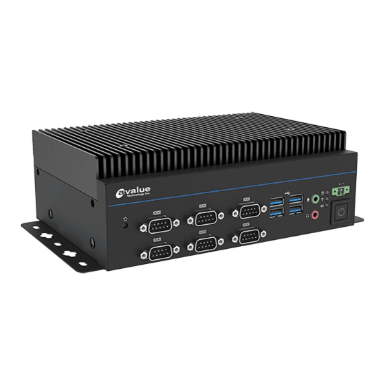
1.4 System Overview 1.4.1 Front View 1.4.2 Rear View Connectors Label Function Note Power Power on button EX PWR Power button 2-Pin Terminal Block Reset Reset button HDD indicator WWAN WWAN Indicator WLAN WLAN Indicator EPS-RPS Quick Reference Guide 23... - Page 24 Serial Port 1~6 connector DC-IN DC Input connector 5-pin Phoenix type (default onboard) HDMI HDMI connector x 2 DP connector x 2 RJ-45 Ethernet x 2 USB2.0 USB 2.0 connector x 2 System Fan Smart Fan connector 24 EPS-RPS Quick Reference Guide...
-
Page 25: System Dimensions
Quick Reference Guide 1.5 System Dimensions (Unit: mm) EPS-RPS Quick Reference Guide 25... -
Page 26: Operating Principle
- Turn ON the system. - Press the power ON/OFF icon firmly to turn power ON/OFF. - The power ON/OFF LED will turn blue to indicate power is on. - Check with the Icon behavior for power status. 26 EPS-RPS Quick Reference Guide... -
Page 27: Hardware Configuration
Quick Reference Guide 2. Hardware Configuration For advanced information, please refer to: 1- EBM-ADS included in this manual. Note: If you need more information, please visit our website: www.avalue.com EPS-RPS Quick Reference Guide 27... -
Page 28: Eps-Rps Connector Mapping
In RS-232 Mode Signal PIN PIN Signal NDCD# NDSR# NRXD NRTS# NTXD NCTS# NDTR# NRI# In RS-422 Mode Signal PIN PIN Signal TxD1- TxD1+ RxD1+ RxD1- In RS-485 Mode Signal PIN PIN Signal DATA1- DATA1+ 28 EPS-RPS Quick Reference Guide... -
Page 29: Serial Port 5~6 Connector (Com5~6)
Quick Reference Guide 2.1.2 Serial Port 5~6 connector (COM5~6) Signal PIN PIN Signal DCD# DSR# RTS# CTS# DTR# 2.1.3 Power button (EX PWR) Signal PWR_BTN_IN 2.1.4 DC Input connector (DC-IN) Signal VIN+ VIN+ CHASSIS_GND VIN- VIN- EPS-RPS Quick Reference Guide 29... -
Page 30: Powering On The System
The supported power input voltages are: ⚫ Power 1 (DIN connector)): 12 V ~ 28 V ⚫ Power 2 (terminal block)): 12 V ~ 28 V Power Input Connector Power Button 30 EPS-RPS Quick Reference Guide... -
Page 31: Ebm-Ads Overviews
Quick Reference Guide 2.4 EBM-ADS Overviews EPS-RPS Quick Reference Guide 31... -
Page 32: Ebm-Ads Jumper & Connector List
1 x 5 terminal block, pitch 5.08 mm SATA_PWR1 SATA power connector 2 x 1 wafer, pitch 2.00 mm DP connector SATA1 Serial ATA connector 1 NGFF_B_1 M.2 KEY-B connector NGFF_E_1 M.2 KEY-E connector NGFF_M_1 M.2 KEY-M connector 32 EPS-RPS Quick Reference Guide... - Page 33 Quick Reference Guide MINI_PCIE1 Full size Mini-PCI-e connector SO_DIMM1/2 DDR5 SODIMM socket 1/2 EPS-RPS Quick Reference Guide 33...
-
Page 34: Setting Jumpers & Connectors
EPS-RPS 2.6 Setting Jumpers & Connectors 2.6.1 Multi-function select (SW1) SW1.1 AT mode ATX mode* *Default SW1.2 M.2 keyB 3.8V M.2 keyB 3.3V* 34 EPS-RPS Quick Reference Guide... -
Page 35: Clear Cmos (Jrtc1)
Quick Reference Guide 2.6.2 Clear CMOS (JRTC1) Normal* Clear CMOS * Default 2.6.3 Serial port 1/2 pin9 signal select (JRI1/2) JRI1 JRI2 Ring* +12V * Default EPS-RPS Quick Reference Guide 35... -
Page 36: Serial Port 1~4 - Rs232/422/485 Mode Select (Jcom_Sel1~4)
EPS-RPS Serial port 1~4 – RS232/422/485 mode select (JCOM_SEL1~4) 2.6.4 RS232* JCOM_SEL4 JCOM_SEL1 RS422, RS485 * Default 2.6.5 Fan connector (JFAN1) Signal +12V TACH_FAN0 PWM_FAN0 36 EPS-RPS Quick Reference Guide... -
Page 37: Serial Port 3/4/5/6 Connector (Jcom3/4)
In RS-232 Mode Signal PIN PIN Signal NDCD# NDSR# NRXD NRTS# NTXD NCTS# NDTR# NRI# In RS-422 Mode Signal PIN PIN Signal TxD1- TxD1+ RxD1+ RxD1- In RS-485 Mode Signal PIN PIN Signal DATA1- DATA1+ EPS-RPS Quick Reference Guide 37... -
Page 38: Serial Port 3/4/5/6 Connector (Jcom5/6)
EPS-RPS 2.6.7 Serial port 3/4/5/6 connector (JCOM5/6) JCOM5 JCOM6 Signal PIN PIN Signal COM_DCD# COM_RXD COM_TXD COM_DTR# COM_DSR# COM_RTS# COM_CTS# COM_RI# 2.6.8 SATA power connector (SATA_PWR1) Signal 38 EPS-RPS Quick Reference Guide... -
Page 39: On-Board Header For Usb2.0 (Jusb1)
Quick Reference Guide 2.6.9 On-board header for USB2.0 (JUSB1) Signal PIN PIN Signal +5VSB +5VSB USB_R_DN5 USB_R_DN4 USB_R_DP5 USB_R_DP4 2.6.10 Front Panel connector (JFP1) Signal Signal FP_PWR_LED+ HDD_LED# PWR_LED# PM_SYSRST# PWRBTN_TO_EC# EPS-RPS Quick Reference Guide 39... -
Page 40: Bios Spi Connector (Bios_Spi1)
EPS-RPS 2.6.11 BIOS SPI connector (BIOS_SPI1) Signal PIN PIN Signal +3.3VSB SPI_CS0# SPI_CLK SPI_MISO SPI_MOSI BIOS_HOLD# BIOS_WP# 2.6.12 ESPI connector (JESPI1) Signal Signal +3.3VSB ESPI_IO0 PLT_RST# ESPI_IO1 ESPI_CS0# ESPI_IO2 ESPI_CLK ESPI_IO3 ESPI_ALEAT# ESPI_RST 40 EPS-RPS Quick Reference Guide... -
Page 41: Power Button (Pwrbtn1)
Quick Reference Guide 2.6.13 Power button (PWRBTN1) Signal PWR_BTN_IN 2.6.14 DC Input connector (JVIN1) Signal +VIN +VIN GND_CHASSIS EPS-RPS Quick Reference Guide 41... -
Page 42: Installation
EPS-RPS 3. Installation 42 EPS-RPS Quick Reference Guide... - Page 43 ⚫ Anti-static Discharge: If a user open the rear panel of the flat bezel panel PC, to configure the jumpers or plug in added peripheral devices, ground themselves first and wear an anti-static wristband. EPS-RPS Quick Reference Guide 43...
-
Page 44: Installing Hard Disk (Eps-Rps)
EPS-RPS 3.1 Installing Hard Disk (EPS-RPS) Step1. Insert and fasten 4 screws on each side of the system to secure brackets. Step2. Fix HDD using the 4 screws in the Accessory Kit. 44 EPS-RPS Quick Reference Guide... - Page 45 Quick Reference Guide Step3. Place back the cover and fasten 6 screws back to complete. EPS-RPS Quick Reference Guide 45...
-
Page 46: Installing Pcie Card (Eps-Rps)
EPS-RPS 3.2 Installing PCIE card (EPS-RPS) Step1. Fasten screw to secure PCIE card. Step2. Place back the cover and fasten 6 screws back to complete. 46 EPS-RPS Quick Reference Guide... -
Page 47: Installing M.2 Key-B Card (Eps-Rps)
Quick Reference Guide 3.3 Installing M.2 Key-B card (EPS-RPS) Step1. Insert M.2 Key-B card into designated locations and fasten with the screw to complete installation. EPS-RPS Quick Reference Guide 47... -
Page 48: Installing M.2 Key-E Card (Eps-Rps)
EPS-RPS 3.4 Installing M.2 Key-E card (EPS-RPS) Step1. Insert M.2 Key-E card into designated locations and fasten with the screw to complete installation. Step2. Place back the cover and fasten 6 screws back to complete. 48 EPS-RPS Quick Reference Guide... -
Page 49: Installing M.2 Key-M Card (Eps-Rps)
Quick Reference Guide 3.5 Installing M.2 Key-M card (EPS-RPS) Step1. Insert M.2 Key-M card into designated locations and fasten with the screw to complete installation. Step2. Fix M.2 M-Key card using the 2 screws in the Accessory Kit. EPS-RPS Quick Reference Guide 49... - Page 50 EPS-RPS Step3. Place back the cover and fasten 6 screws back to complete. 50 EPS-RPS Quick Reference Guide...
-
Page 51: Installing Din Rail Mounting (Eps-Rps)
Quick Reference Guide 3.6 Installing Din Rail Mounting (EPS-RPS) (Horizontal Din Rail) (Vertical Din Rail) Step1. Insert Din Rail into designated locations and fasten with the 4 screws to complete installation. EPS-RPS Quick Reference Guide 51... -
Page 52: System Mounting
Keep the wires separated according to the interface. Wires that share similar electrical characteristics must be bundled together. ⚫ Do not bundle input wiring with output wiring. Keep them separate. ⚫ When necessary, it is strongly advised that you label wiring to all devices in the system. 52 EPS-RPS Quick Reference Guide... -
Page 53: Drivers Installation
HID touch digitizer built-in driver in Windows 7 or later. Note: Installation procedures and screen shots in this section are for your reference and may not be exactly the same as shown on your screen. EPS-RPS Quick Reference Guide 53... -
Page 54: Install Chipset Driver
Windows 11 operation system. If the warning message appears while the installation process, click Continue to go on. Step 3. Click Install. Step 4. Click Finish to complete setup. Step1. Click Next. Step 2. Click Accept. 54 EPS-RPS Quick Reference Guide... -
Page 55: Install Vga Driver
Windows 11 operation system. Step 3. Click Start. Step 1. Click Begin installation to Step 4. Click Finish to complete setup. continue installation. Step 2. Click I agree. EPS-RPS Quick Reference Guide 55... -
Page 56: Install Audio Driver (For Realtek Alc888S Hd Audio)
Windows 11 operation system. If the warning message appears while the installation process, click Continue to go on. Step1. Click Next to Install. Step 2. Select Finish to complete Installation. 56 EPS-RPS Quick Reference Guide... -
Page 57: Install Lan Driver
Windows 11 operation system. Step 3. Click Next. Step 1. Click Install Drivers and Step 4. Click Next. Software to continue installation. Step 2. Click Next. Step 5. Click Install. EPS-RPS Quick Reference Guide 57... - Page 58 EPS-RPS Step 6. Click Finish to complete setup. 58 EPS-RPS Quick Reference Guide...
-
Page 59: Install Serial Io Driver
Windows 11 operation system. Step 3. Click Next. Step 1. Click Next to continue setup. Step 4. Click Next. Step 2. Click Next. Step 5. Click Finish to complete the setup. EPS-RPS Quick Reference Guide 59... -
Page 60: Install Me Driver
Note: The installation procedures and screen shots in this section are based on Windows 11 operation system. Step 3. Click Next Step 4. Click Finish to complete the setup Step 1. Click Next to continue setup. Step 2. Click Next. 60 EPS-RPS Quick Reference Guide... -
Page 61: Install Irst Driver
Windows 11 operation system. Step 3. Click Next. Step 1. Click Next to continue installation. Step 4. Click Next. Step 2. Click Next. Step 5. Complete setup. EPS-RPS Quick Reference Guide 61... -
Page 62: Bios Setup
EPS-RPS 5.BIOS Setup 62 EPS-RPS Quick Reference Guide... -
Page 63: Introduction
If you do not press the keys at the correct time and the system does not boot, an error message will be displayed and you will again be asked to. Press F1 to Continue, DEL to enter SETUP EPS-RPS Quick Reference Guide 63... -
Page 64: Using Setup
Note: Some of the navigation keys differ from one screen to another. • To Display a Sub Menu Use the arrow keys to move the cursor to the sub menu you want. Then press <Enter>. A “➢” pointer marks all sub menus. 64 EPS-RPS Quick Reference Guide... -
Page 65: Getting Help
BIOS Vendor and your systems manufacturer to provide the absolute maximum performance and reliability. Even a seemingly small change to the chipset setup has the potential for causing you to use the override. EPS-RPS Quick Reference Guide 65... -
Page 66: Bios Setup
<Enter> to accept and enter the sub-menu. 5.6.1 Main Menu This section allows you to record some basic hardware configurations in your computer and set the system clock. 66 EPS-RPS Quick Reference Guide... -
Page 67: System Language
Visit the Avalue website (www.avalue.com) to download the latest product and BIOS information. 5.6.2 Advanced Menu This section allows you to configure your CPU and other system devices for basic operation through the following sub-menus. EPS-RPS Quick Reference Guide 67... -
Page 68: Cpu Configuration
Number of cores to enable in each processor package. Note: Number of Cores and E-cores are Active Performance-cores looked at together. When both are {0,0}, Pcode will enable all cores. Disabled Hyper-Threading Enable or Disable Hyper-Threading Technology. Enabled[Default] 68 EPS-RPS Quick Reference Guide... -
Page 69: Performance-Core Information
Allows more than two frequency ranges to be Intel® SpeedStep™ Enabled[Default] supported. Enable/Disable intel® Speed Shift Technology Intel® Speed Shift Disabled support. Enabling will expose the CPPC v2 interface Technology Enabled[Default] to allow for hardware controlled P-states. EPS-RPS Quick Reference Guide 69... -
Page 70: Pch-Fw Configuration
C States Disabled CPU to go to C states when it’s not 100% utilized 5.6.2.2 PCH-FW Configuration 5.6.2.2.1 Firmware Update Configuration Item Option Description Disabled[Default], Me FW Image Re-Flash Enable/Disable Me FW Image Re-Flash function. Enabled 70 EPS-RPS Quick Reference Guide... -
Page 71: Ptt Configuration
5.6.2.3 Trusted Computing Item Options Description Enables or Disables BIOS support for security device. Disable, Security Device Support O.S. will not show Security Device. TCG EFI protocol Enable[Default] and INT1A interface will not be available. EPS-RPS Quick Reference Guide 71... -
Page 72: Apci Settings
Enable Hibernation Enabled[Default], option may not be effective with some Select the highest ACPI sleep state the Suspend Disabled, ACPI Sleep State system will enter when the SUSPEND S3 (Suspend to RAM)[Default] button is pressed. 72 EPS-RPS Quick Reference Guide... -
Page 73: Super Io Configuration
Set Parameters of Serial Port 3 (COMC). Serial Port 4 Configuration Set Parameters of Serial Port 4 (COMD). Serial Port 5 Configuration Set Parameters of Serial Port 5 (COME). Serial Port 6 Configuration Set Parameters of Serial Port 6 (COMF). EPS-RPS Quick Reference Guide 73... -
Page 74: Serial Port 1 Configuration
Disabled RS232[Default], Set COM Port as RS232, RS422 or UART 232 422 485 RS422 RS485 mode. RS485 5.6.2.5.2 Serial Port 2 Configuration Item Option Description Enabled[Default], Serial Port Enable or Disable Serial Port (COM). Disabled 74 EPS-RPS Quick Reference Guide... -
Page 75: Serial Port 3 Configuration
5.6.2.5.3 Serial Port 3 Configuration Item Option Description Enabled[Default], Serial Port Enable or Disable Serial Port (COM). Disabled RS232[Default], Set COM Port as RS232, RS422 or UART 232 422 485 RS422 RS485 mode. RS485 5.6.2.5.4 Serial Port 4 Configuration EPS-RPS Quick Reference Guide 75... -
Page 76: Serial Port 5 Configuration
Disabled RS232[Default], Set COM Port as RS232, RS422 or UART 232 422 485 RS422 RS485 mode. RS485 5.6.2.5.5 Serial Port 5 Configuration Item Option Description Enabled[Default], Serial Port Enable or Disable Serial Port (COM). Disabled 76 EPS-RPS Quick Reference Guide... -
Page 77: Serial Port 6 Configuration
Quick Reference Guide 5.6.2.5.6 Serial Port 6 Configuration Item Option Description Enabled[Default], Serial Port Enable or Disable Serial Port (COM). Disabled 5.6.2.6 NCT6126D HW Monitor EPS-RPS Quick Reference Guide 77... -
Page 78: Smart Fan Mode Configuration
Select: Mode 01 to Mode 20 10/Mode 11/Mode 12/Mode 13/Mode Or Manual(No Smart Fan). 14/Mode 15/Mode 16/Mode 17/Mode 18/Mode 19/Mode 20 Set Fan Duty SYS Fan Manual Mode Duty Manually(1~255). 5.6.2.7 S5 RTC Wake Settings 78 EPS-RPS Quick Reference Guide... -
Page 79: Serial Port Console Redirection
Wake system from S5 Fixed Time Select Dynamic Time, System will wake on the current time Dynamic Time + Increase minute(s). 5.6.2.8 Serial Port Console Redirection Item Options Description Disabled[Default], Console Redirection Console Redirection Enable or Disable. Enabled EPS-RPS Quick Reference Guide 79... -
Page 80: Usb Configuration
Auto[Default] Floppy enumerates devices according to their media Mass Storage Devices Forced FDD format. Optical drives are emulated as ‘CDROM’, drives with no media will be Hard Disk CD-ROM emulated according to a drive type. 80 EPS-RPS Quick Reference Guide... -
Page 81: Network Stack Configuration
Quick Reference Guide 5.6.2.10 Network Stack Configuration Item Options Description Enabled Network Stack Enable/Disable UEFI Network Stack. Disabled[Default] 5.6.2.11 NVMe Configuration EPS-RPS Quick Reference Guide 81... -
Page 82: Chipset
EPS-RPS 5.6.3 Chipset 5.6.3.1 System Agent (SA) Configuration Item Option Description Enabled[Default] VT-d VT-d capability. Disabled 82 EPS-RPS Quick Reference Guide... -
Page 83: Memory Configuration
5.6.3.1.1 Memory Configuration 5.6.3.1.2 Graphics Configuration Item Option Description Select which of IGFX/PEG/PCI Graphics device Auto[Default] Primary Display should be Primary Display Or select SG for IGFX Switchable Gfx. GTT Size Select the GTT Size. 8MB[Default] EPS-RPS Quick Reference Guide 83... -
Page 84: Dmi/Opi Configuration
EPS-RPS 5.6.3.1.3 DMI/OPI Configuration 5.6.3.2 PCH-IO Configuration Item Option Description Disabled PCH LAN Controller Enable/Disable onboard NIC. Enabled[Default] 84 EPS-RPS Quick Reference Guide... -
Page 85: Pci Express Configuration
Item Option Description Enabled[Default], M.2 KeyE (PCI-E Port 1) Control the PCI Express Root Port. Disabled Set the ASPM Level: Force L0s – Force all Disabled[Default] ASPM links to L0s State AUTO – BIOS auto EPS-RPS Quick Reference Guide 85... -
Page 86: Mini Card (Pci-E Port 2)
Disabled[Default] all links to L0s State AUTO – BIOS auto ASPM configure DISABLE – Disables ASPM. Auto Disabled, L1 Substates L1.1 PCI Express L1 Substates settings. L1.1 & L1.2[Default] Disabled Enable/Disable Precision Time Enabled[Default] Measurement. 86 EPS-RPS Quick Reference Guide... -
Page 87: Intel I225/I226 Lan Chip (Pci-E Port 4)
Configure PCIe Speed. Gen2 Gen3 The number of milliseconds reference code will wait for link to exit Detect state for enabled Detect Timeout ports before assuming there is no device and potentially disabling the port. EPS-RPS Quick Reference Guide 87... -
Page 88: Keyb (Pci-E Port 5~6)
Configure PCIe Speed. Gen2 Gen3 The number of milliseconds reference code will wait for link to exit Detect state for enabled Detect Timeout ports before assuming there is no device and potentially disabling the port. 88 EPS-RPS Quick Reference Guide... -
Page 89: Sata Configuration
The Mode Enable/Disable (Loop Back). Disabled[Default] Enabled[Default] SATA Port Enable or Disable SATA Port. Disabled Hard Disk Drive[Default] Identify the SATA port is connected to Solid SATA Device Type Solid State Drive State Drive or Hard Disk Drive. EPS-RPS Quick Reference Guide 89... -
Page 90: Hd Audio Configuration
HD Audio Configuration Item Option Description Control Detection of the HD-Audio device. Disable = HDA Disabled HD Audio will be unconditionally disabled Enabled = HDA will be Enabled[Default] unconditionally enabled 5.6.3.3 Board & Panel Configuration 90 EPS-RPS Quick Reference Guide... -
Page 91: Security
Disabled[Default] Enabled/Disabled M.2 KeyB 5G Card M.2 KeyB 5G Workaround Enabled Workaround. SUSCLK[Default] PCH GPD8 Set PCH GPD8 funciton for some 5G card. Output low Disabled[Default] SHOW DMI INFO SHOW DMI INFO. Enabled 5.6.4 Security EPS-RPS Quick Reference Guide 91... -
Page 92: Secure Boot
EPS-RPS ⚫ Administrator Password Set setup Administrator Password ⚫ User Password Set User Password 5.6.4.1 Secure Boot 5.6.5 Boot 92 EPS-RPS Quick Reference Guide... -
Page 93: Save And Exit
This option restores all BIOS settings to the factory default. This option is useful if the controller exhibits unpredictable behavior due to an incorrect or inappropriate BIOS setting. 5.6.6.4 Launch EFI Shell from filesystem device Attempts to Launch EFI Shell application (Shellx64.efi) from one of the available filesystem devices. EPS-RPS Quick Reference Guide 93... -
Page 94: Maintenance & Troubleshooting
System Maintenance Introduction If the components of the product fail they must be replaced. Please contact the system reseller or vendor to purchase the replacement parts. Please follow the safety precautions outlined in the sections that follow 94 EPS-RPS Quick Reference Guide... - Page 95 Drop the device against a hard surface. ⚫ Strike or exert excessive force onto the LCD panel. ⚫ Touch any of the LCD panels with a sharp object. ⚫ In a site where the ambient temperature exceeds the rated temperature. EPS-RPS Quick Reference Guide 95...
- Page 96 This reduces the possibility of ESD damage. ⚫ Only handle the edges of the electrical component. When handling the electrical component, hold the electrical component by its edges. Please ensure the following safety precautions are adhered to at all times. 96 EPS-RPS Quick Reference Guide...
- Page 97 Never drop any objects or liquids through the openings of the device. ⚫ Be cautious of any possible allergic reactions to solvents or chemicals used when cleaning the device. ⚫ Avoid eating, drinking and smoking within vicinity of the device. EPS-RPS Quick Reference Guide 97...
- Page 98 Cotton swabs: Cotton swaps moistened with rubbing alcohol or water are excellent tools for wiping hard to reach areas. ⚫ Foam swabs: Whenever possible, it is best to use lint free swabs such as foam swabs for cleaning. 98 EPS-RPS Quick Reference Guide...
- Page 99 No Console Input Devices are found Flash update is failed Typically for development use. The beep code is generated when platform cannot be reset because reset protocol is not available. Platform PCI resource requirements cannot be met EPS-RPS Quick Reference Guide 99...
-
Page 100: Product Application
Avalue technical support team, or Avalue customer service representatives for further information. Feel free to inquire about this supplementary resource to enhance your understanding of the Watchdog Timer and Digital I/O (DIO) Application for optimal utilization of your Panel 100 EPS-RPS Quick Reference Guide... -
Page 101: Operating The Device
Avalue technical support team, or Avalue customer service representatives. These professionals can provide tailored guidance and assistance to address any unique needs related to Multi-Touch mode adjustments. EPS-RPS Quick Reference Guide 101...
Need help?
Do you have a question about the EPS-RPS and is the answer not in the manual?
Questions and answers