Table of Contents
Advertisement
Quick Links
Download this manual
See also:
User Manual
Advertisement
Table of Contents

Related Manuals for Avalue Technology ECM-945GSE


Summary of Contents for Avalue Technology ECM-945GSE
-
Page 1: Quick Installation Guide
ECM-945GSE Intel® Atom™ processor N270 3.5” Micro Module with Intel® 945GSE + ICH7-M Chipset Quick Installation Guide Ed – 06 November 2009 Part No. E2017381602R... -
Page 2: Getting Started
Before you begin installing your single board, please make sure that the following materials have been shipped: 1 x Intel® 945GSE Micro Module 1 x Quick Installation Guide for ECM-945GSE 1 x AUX-021 daughter board 1 x DVD-ROM contains the followings: —... - Page 3 Quick Installation Guide 2. Hardware Configuration ECM-945GSE Quick Installation Guide 3...
-
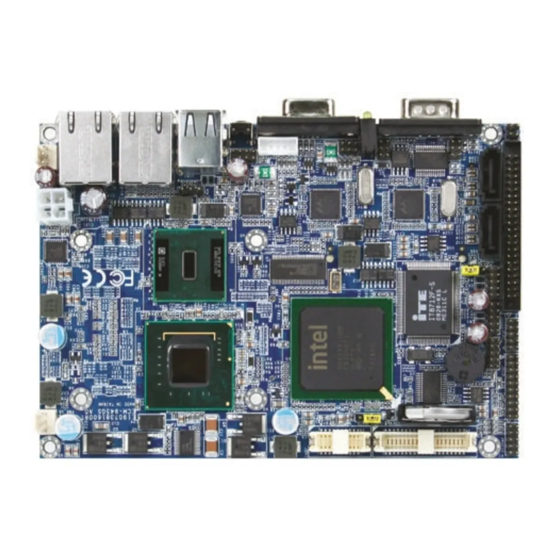
Page 4: Product Overview
ECM-945GSE Quick Installation Guide 2.1 Product Overview 4 ECM-945GSE Quick Installation Guide... -
Page 5: Jumper And Connector List
3 x 1 header, pitch 2.54mm JBAT1 CF mode select 3 x 1 header, pitch 2.54mm AT/ATX mode select 2 x 1 header, pitch 2.0mm PWR_MSEL Input Power type select 3 x 1 header, pitch 2.54mm PWR_5VSEL ECM-945GSE Quick Installation Guide 5... - Page 6 2 x 2 header, pitch 2.0mm Power connector PWRCON Reset button RSTBTN Serial ATA connector 1 SATA1 Serial ATA connector 2 SATA2 USB connector 0 & 1 USB1 (Co-lay with KB/MS ) VGA connector D-sub 15-pin, female 6 ECM-945GSE Quick Installation Guide...
-
Page 7: Setting Jumpers & Connectors
Quick Installation Guide 2.3 Setting Jumpers & Connectors 2.3.1 AT/ATX mode select (PWR_MSEL) PWR_MSEL * Default JPWRBTN Signal PWR_BT Note: JPWRBTN is available in ATX mode. ECM-945GSE Quick Installation Guide 7... - Page 8 ECM-945GSE Quick Installation Guide 2.3.2 Input Power type select (PWR_5VSEL) AT Type * ATX Type * Default 2.3.3 5VSB Power connector in ATX Type (PWR_SB) Signal PSON# 5VSB Note: Connect PWR_SB with cable in ATX type power-input. 8 ECM-945GSE Quick Installation Guide...
- Page 9 ATX mode. AT Mode (PWR_MSEL) Use ATX type power input, and set ATX type the board in AT mode. (PWR_5VSEL) ATX Mode (PWR_MSEL) Use ATX type power input, and set the board in ATX mode. ECM-945GSE Quick Installation Guide 9...
- Page 10 ECM-945GSE Quick Installation Guide 2.3.4 Clear CMOS (JBAT) Protect* Clear CMOS * Default 2.3.5 CF Mode select (JCF) Master* Slave * Default 10 ECM-945GSE Quick Installation Guide...
- Page 11 Quick Installation Guide 2.3.6 Audio connector (JAUDIO) Signal PIN PIN Signal LIN-OUT_R LIN-OUT-L LIN-IN-R LIN-IN-L MIC_IN MIC_REF 2.3.7 CPU Fan connector (CPU_FAN) Signal +12V FAN_TAC1 ECM-945GSE Quick Installation Guide 11...
- Page 12 ECM-945GSE Quick Installation Guide 2.3.8 General purpose I/O connector (JDIO1) Signal Signal DO_GP20 DI_GP30 DO_GP21 DI_GP31 DO_GP22 DI_GP32 DO_GP23 DI_GP33 DO_GP24 DI_GP34 DO_GP25 DI_GP35 DO_GP26 DI_GP36 DO_GP27 DI_GP37 SMB_CLK SMB_DATA 2.3.9 Serial port 2 connector (JCOM2) Signal Signal 12 ECM-945GSE Quick Installation Guide...
- Page 13 Quick Installation Guide 2.3.10 Serial Port 2 in RS-422/485 (J422/485) Signal Signal TxD- RxD- TxD+ RxD+ Note: J422/485 is available after modifying the mode of COM2 in BIOS setting. 2.3.11 TV connector (JTV) Signal Signal CVBS ECM-945GSE Quick Installation Guide 13...
- Page 14 ECM-945GSE Quick Installation Guide 2.3.12 Power Connector (PWRCON) Signal PIN PIN Signal 2.3.13 LCD backlight brightness adjustment connector (JVR) Signal Variation Resistor (Recommended: 4.7KΩ, >1/16W) 14 ECM-945GSE Quick Installation Guide...
- Page 15 VR signal controlled by JVR. Please see the JVR section for detailed circuitry information. 2.3.14.1 Signal Description – LCD Inverter Connector (JBKL) Signal Signal Description Vadj = 0.75V ~ 4.25V (Recommended: 4.7KΩ, >1/16W) ENBKL LCD backlight ON/OFF control signal ECM-945GSE Quick Installation Guide 15...
- Page 16 ECM-945GSE Quick Installation Guide 2.3.15 USB Connector 2, 3, 4 &5 (JUSB2, JUSB3) Signal PIN PIN Signal D2-/D4- D2+/D4+ D3+/D5+ D3-/D5- 16 ECM-945GSE Quick Installation Guide...
- Page 17 Txout2# Txout3# E_Txout0 E_Txout1 E_Txout0 E_Txout1 E_Txout0# 24 23 E_Txout1# E_Txout0# 24 23 E_Txout1# E_Txout2 E_Txout2 E_Txout3 E_Txout2# 30 E_Txout2# 30 29 E_Txout3# Txclk E_Txclk Txclk E_Txclk Txclk# E_Txclk# Txclk# E_Txclk# +12V +12V +12V +12V ECM-945GSE Quick Installation Guide 17...
- Page 18 ECM-945GSE Quick Installation Guide 2.3.17 DVI connector (JDVI) Signal PIN PIN Signal TDC0# TDC0 HPDET TDC1# DDC_DAT TDC1 DDC_CLK TLC# TDC2# TDC2 2.3.18 Keyboard & mouse connector (JKB/MS) Signal Signal 18 ECM-945GSE Quick Installation Guide...
- Page 19 5 x 2 header, pitch 2.0mm Audio connector 2.0mm USB connector 5 x 2 header, pitch 2.0mm 2.0mm USB connector 5 x 2 header, pitch 2.0mm TV / Audio connector (Optional) 8 x 2 header, pitch 2.54mm TV out connector ECM-945GSE Quick Installation Guide 19...
- Page 20 TV / Audio Connector (JP7) (JP4) ignal PIN PIN Signal Signal PIN PIN Signal Signal Signal Mic In Mic Bais Line out L Line out R SPK L SPK R Line in L Line in R TVGND TVGND COMP 20 ECM-945GSE Quick Installation Guide...
Need help?
Do you have a question about the ECM-945GSE and is the answer not in the manual?
Questions and answers