
Subscribe to Our Youtube Channel
Related Manuals for Avalue Technology ECM-TGUC


Summary of Contents for Avalue Technology ECM-TGUC
- Page 1 ECM-TGUC 11th Gen Intel® Core™ SoC i5/i3 BGA Processor 3.5” Micro Module User’s Manual Ed –17 August 2022 Part No. E2047395600R...
- Page 2 Disclaimer Avalue Technology Inc. reserves the right to make changes, without notice, to any product, including circuits and/or software described or contained in this manual in order to improve design and/or performance. Avalue Technology assumes no responsibility or liability for the...
- Page 3 Applications that are described in this manual are for illustration purposes only. Avalue Technology Inc. makes no representation or warranty that such application will be suitable for the specified use without further testing or modification.
- Page 4 A product returned without proof of the purchase date is not eligible for warranty service. Write the RMA number visibly on the outside of the package and ship it prepaid to your dealer. 4 ECM-TGUC User’s Manual...
-
Page 5: Table Of Contents
PC Buzzer connector (JBZ1) ..................... 30 2.3.21 AMP connector (JAMP1) ......................31 2.3.22 BIOS connector (JBIOS1) ......................31 2.3.23 eSPI debug connector (JESPI1) ....................32 2.3.24 Audio connector (JAUDIO1) ...................... 32 Signal Description – Audio connector (JAUDIO1) ..............32 2.3.24.1 ECM-TGUC User’s Manual... - Page 6 Chipset............................51 3.6.3.1 System Agent (SA) Configuration ..................52 3.6.3.1.1 Memory Configuration ......................52 3.6.3.1.2 Graphics Configuration ......................53 3.6.3.1.3 VMD setup menu ........................53 3.6.3.2 PCH-IO Configuration ......................54 3.6.3.2.1 PCI Express Configuration ....................54 6 ECM-TGUC User’s Manual...
- Page 7 Install VGA Driver ....................68 Install ME Driver ...................... 69 Install LAN Driver ....................70 Install Serial IO Driver ..................... 72 Install Audio Driver (For Realtek ALC888S) ............73 Install Realtek Audio Control Driver ................ 74 5. Mechanical Drawing ....................75 ECM-TGUC User’s Manual...
-
Page 8: Getting Started
1.2 Packing List Before you begin installing your single board, please make sure that the following materials have been shipped: 1 x 3.5” ECM-TGUC Micro Module 1 x Serial ATA cable (7-pin, standard) 1 x Wire SATA power cable ... -
Page 9: Document Amendment History
User’s Manual 1.3 Document Amendment History Revision Date Comment August 2022 Avalue Initial Release ECM-TGUC User’s Manual... -
Page 10: Manual Objectives
We strongly recommend that you study this manual carefully before attempting to set up ECM-TGUC or change the standard configurations. Whilst all the necessary information is available in this manual we would recommend that unless you are confident, you contact your supplier for guidance. -
Page 11: System Specifications
SATA 1 x SATA III Edge I/O 1 x Intel® I219LM Gigabit Ethernet PHY 1 x Intel® I225V Gigabit Ethernet USB 2.0 1 x USB 2.0 3 x USB 3.2 Gen 2x1 USB 3.1 2x DP++ ECM-TGUC User’s Manual 11... - Page 12 Intel® Tiger Lake UP3 SoC Processor integrated Gen12 graphics Graphic Chipset Intel resolution: Spec. & Resolution 2 x DP++ 1.4 : 4096 x 2304@60 Hz 1 x LVDS: 1920 x 1080 Dual channel 18/24-bits LVDS (Chrontel 12 ECM-TGUC User’s Manual...
- Page 13 Reference IEC60068-2-64 Testing procedures Test Fh: Vibration broadband random Test 1. PSD: 0.026G²/Hz, 2.16 Grms Vibration Test 2. Non-operation mode 3. Test Frequency: 5-500Hz 4. Test Axis: X,Y and Z axis 5. 30 min. per each axis ECM-TGUC User’s Manual 13...
- Page 14 1. JLVDS1 connector support 1 x 2CH LVDS or 1x eDP, by BIOS select to eDP and use with eDP panel. 2. N_SIM1 and JN_SIM1 can’t be using at the same time, user need to choose either one. 14 ECM-TGUC User’s Manual...
-
Page 15: Architecture Overview-Block Diagram
User’s Manual 1.6 Architecture Overview—Block Diagram The following block diagram shows the architecture and main components of ECM-TGUC ECM-TGUC User’s Manual 15... -
Page 16: Hardware Configuration
ECM-TGUC User’s Manual 2. Hardware Configuration 16 ECM-TGUC User’s Manual... -
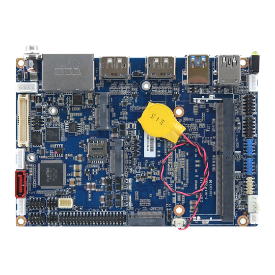
Page 17: Product Overview
User’s Manual 2.1 Product Overview ECM-TGUC User’s Manual 17... -
Page 18: Jumper And Connector List
M.2 Key B power level select 3 x 1 header, pitch 2.00mm Connectors Label Function Note 5 x 1 wafer, pitch 2.00mm LCD inverter backlight connector JBKL1 Matching Connector: JST PHR-5 JC_FAN1 CPU fan connector 4 x 1 wafer, pitch 2.54mm 18 ECM-TGUC User’s Manual... - Page 19 Audio connector 6 x 2 header, pitch 2.00mm N_SIM1 SIM card slot Amp connector 4 x 1 wafer, pitch 2.00mm JAMP1 DC Jack lockable connector SIM card slot 10 x 1 FPC, pitch 0.50 mm JN_SIM1 ECM-TGUC User’s Manual 19...
-
Page 20: Setting Jumpers & Connectors
ECM-TGUC User’s Manual 2.3 Setting Jumpers & Connectors 2.3.1 Serial port 2 pin9 signal select (JRI2) Ring* +12V * Default 2.3.2 Clear CMOS (JRTC1) Normal* Clear CMOS * Default 20 ECM-TGUC User’s Manual... -
Page 21: At/Atx Input Power Select (Jat1)
User’s Manual 2.3.3 AT/ATX Input power select (JAT1) * Default 2.3.4 Flash Descriptor Security Override (JME1) Enable (No Over-ride)* Disable (Over-ride) * Default ECM-TGUC User’s Manual 21... -
Page 22: Key B Power Level Select (Jsel1)
ECM-TGUC User’s Manual 2.3.5 M.2 Key B power level select (JSEL1) 3.3V* 3.8V * Default 2.3.6 LCD inverter connector (JBKL1) Signal +12V BKLEN VBRIGHT 22 ECM-TGUC User’s Manual... -
Page 23: Serial Port 1 Connector (Jcom1)
2.3.7 Serial port 1 connector (JCOM1) Signal PIN PIN Signal COM_RI#_1 COM_CTS#_1 COM_RTS#_1 COM_DSR#_1 COM_DTR#_1 COM_TXD_1 COM_RXD_1 COM_DCD#_1 2.3.8 Serial port 2 connector (JCOM2) Signal PIN PIN Signal +V12S_COM_RI#_2 COM_CTS#_2 COM_RTS#_2 COM_DSR#_2 COM_DTR#_2 COM_TXD_2 COM_RXD_2 COM_DCD#_2 ECM-TGUC User’s Manual 23... -
Page 24: Serial Port 3-6 Connector (Jcom3_6)
Signal PIN PIN Signal COM_RI#_6 COM_CTS#_6 COM_RTS#_6 COM_DSR#_6 COM_DTR#_6 COM_TXD_6 COM_RXD_6 COM_DCD#_6 COM_RI#_5 COM_CTS#_5 COM_RTS#_5 COM_DSR#_5 COM_DTR#_5 COM_TXD_5 COM_RXD_5 COM_DCD#_5 COM_RI#_4 COM_CTS#_4 COM_RTS#_4 COM_DSR#_4 COM_DTR#_4 COM_TXD_4 COM_RXD_4 COM_DCD#_4 COM_RI#_3 COM_CTS#_3 COM_RTS#_3 COM_DSR#_3 COM_DTR#_3 COM_TXD_3 COM_RXD_3 COM_DCD#_3 24 ECM-TGUC User’s Manual... -
Page 25: Serial Port 1 In Rs-422/485 Mode (J422485)
User’s Manual 2.3.10 Serial port 1 in RS-422/485 mode (J422485) Signal PIN PIN Signal +V5S_422485 422_RXDN 422_RXDP 485-422_TXDP 485-422_TXDN 2.3.11 CPU fan connector (JC_FAN1) Signal +12V CPUFAN_IN CPUFAN_OUT ECM-TGUC User’s Manual 25... -
Page 26: General Purpose I/O Connector (Jdio1)
ECM-TGUC User’s Manual 2.3.12 General purpose I/O connector (JDIO1) Signal PIN PIN Signal DIO_GP20 DIO_GP10 DIO_GP21 DIO_GP11 DIO_GP22 DIO_GP12 DIO_GP23 DIO_GP13 SMB_SCL_S0 SMB_SDA_S0 2.3.13 SATA Power connector (JSATA_PWR1) Signal +12V 26 ECM-TGUC User’s Manual... -
Page 27: Battery Connector (Jbat1)
User’s Manual 2.3.14 Battery connector (JBAT1) Signal +RTCBAT 2.3.15 Power connector (JPWR1) Signal +24VSB +24VSB ECM-TGUC User’s Manual 27... -
Page 28: Lvds Connector (Jlvds1)
Signal PIN PIN Signal +3.3V +3.3V +3.3V LVDS_A_DATA_P_1/ LVDS_A_DATA_P_0/ eDP_TX1P eDP_HPD LVDS_A_DATA_N_1/ LVDS_A_DATA_N_0 eDP_TX1N LVDS_A_DATA_P_2/ LVDS_A_DATA_P_3 eDP_TX0P LVDS_A_DATA_N_2/ LVDS_A_DATA_N_3 eDP_TX0N LVDS_B_DATA_P_1 LVDS_B_DATA_P_0 LVDS_B_DATA_N_1 LVDS_B_DATA_N_0 LVDS_B_DATA_P_3 LVDS_B_DATA_P_2 LVDS_B_DATA_N_3 LVDS_B_DATA_N_2 LVDS_A_CLK_P/ LVDS_B_CLK_P eDP_AUXP LVDS_A_CLK_N/ LVDS_B_CLK_N eDP_AUXN +12V +12V 28 ECM-TGUC User’s Manual... -
Page 29: Usb2.0 Connector (Jusb56)
User’s Manual 2.3.17 USB2.0 connector (JUSB56) Signal PIN PIN Signal +5VSB +5VSB USB_R_DN5 USB_R_DN6 USB_R_DP5 USB_R_DP6 2.3.18 USB2.0 connector (JUSB78) Signal PIN PIN Signal +5VSB +5VSB USB_R_DN7 USB_R_DN8 USB_R_DP7 USB_R_DP8 ECM-TGUC User’s Manual 29... -
Page 30: Front Panel Connector (Jfp1)
ECM-TGUC User’s Manual 2.3.19 Front Panel connector (JFP1) Signal PIN PIN Signal HDD_LED_P PWR_LED_P HDD_LED# PWR_LED# PM_SYSRST# PWRBTN_IN# 2.3.20 PC Buzzer connector (JBZ1) Signal SOC_SPKR_R 30 ECM-TGUC User’s Manual... -
Page 31: Amp Connector (Jamp1)
User’s Manual 2.3.21 AMP connector (JAMP1) Signal AMP_LOUT+ AMP_LOUT- AMP_ROUT+ AMP_ROUT- 2.3.22 BIOS connector (JBIOS1) Signal PIN PIN Signal +V3.3A_SPI SPI_CS0#_ROM SPI_CLK_ROM SPI_MISO_ROM SPI_MOSI_ROM SPI_HOLD#_ROM SPI_WP#_ROM ECM-TGUC User’s Manual 31... -
Page 32: Espi Debug Connector (Jespi1)
HD_AGND HD_AGND LINE1-R-IN LINE1-L-IN MIC1-R-IN MIC1-L-IN FRONT-JD LINE1-JD MIC1-JD HD_AGND 2.3.24.1 Signal Description – Audio connector (JAUDIO1) Signal Signal Description LINE1-JD AUDIO IN (LINE_RIN/LIN)sense pin FRONT-JD AUDIO Out(ROUT/LOUT) sense pin MIC1-JD MIC IN (MIC_RIN/LIN) sense pin 32 ECM-TGUC User’s Manual... -
Page 33: Sim Card Slot (Jn_Sim1)
User’s Manual 2.3.25 SIM card slot (JN_SIM1) Signal N_SIM_CD_R UIM_DATA_R UIM_CLK_R +VPP_SIM_1 UIM_RESET# +VCC_SIM ECM-TGUC User’s Manual 33... -
Page 34: Bios Setup
ECM-TGUC User’s Manual 3.BIOS Setup 34 ECM-TGUC User’s Manual... -
Page 35: Introduction
If the message disappears before you respond and you still wish to enter Setup, restart the system to try again by turning it OFF then ON or pressing the "RESET" button on the system case. You may also restart by simultaneously pressing <Ctrl>, <Alt>, and <Delete> keys. ECM-TGUC User’s Manual 35... -
Page 36: Using Setup
Note: Some of the navigation keys differ from one screen to another. To Display a Sub Menu Use the arrow keys to move the cursor to the sub menu you want. Then press <Enter>. A “” pointer marks all sub menus. 36 ECM-TGUC User’s Manual... -
Page 37: Getting Help
BIOS Vendor and your systems manufacturer to provide the absolute maximum performance and reliability. Even a seemingly small change to the chipset setup has the potential for causing you to use the override. ECM-TGUC User’s Manual 37... -
Page 38: Bios Setup
<Enter> to accept and enter the sub-menu. 3.6.1 Main Menu This section allows you to record some basic hardware configurations in your computer and set the system clock. 38 ECM-TGUC User’s Manual... -
Page 39: System Language
Visit the Avalue website (www.avalue.com.tw) to download the latest product and BIOS information. 3.6.2 Advanced Menu This section allows you to configure your CPU and other system devices for basic operation through the following sub-menus. ECM-TGUC User’s Manual 39... -
Page 40: Cpu Configuration
Item Options Description When enabled, a VMM can utilize the additional Intel (VMX) Virtualization Disabled hardware capabilities provided by Vanderpool Technology Enabled[Default] Technology. All[Default] Number of cores to enable in each processor Active Processor Cores package. 40 ECM-TGUC User’s Manual... -
Page 41: Power & Performance
Allows more than two frequency ranges to be Intel® SpeedStep™ Disabled supported. Eanble/Disable Intel® Speed Shift Technology Intel® Speed Shift Enabled[Default], support. Enabling will expose the CPPC v2 interface to Technology Disabled allow for hardware controlled P-states. ECM-TGUC User’s Manual 41... -
Page 42: Pch-Fw Configuration
Disabled enabled). Enabled[Default], C States Enable/Disable CPU Power Management. Disabled Enabled[Default], Enable/Disable C1E. When enabled, CPU will switch Enhanced C-States Disabled to minimum speed when all cores enter C-State. 3.6.2.3 PCH-FW Configuration 3.6.2.3.1 Firmware Update Configuration 42 ECM-TGUC User’s Manual... -
Page 43: Trusted Computing
3.6.2.4 Trusted Computing Item Options Description Enables or Disables BIOS support for security device. Disable, Security Device Support O.S. will not show Security Device. TCG EFI protocol Enable[Default] and INT1A interface will not be available. 3.6.2.5 APCI Settings ECM-TGUC User’s Manual 43... -
Page 44: Super Io Configuration
Set Parameters of Serial Port 3 (COMC). Serial Port 4 Configuration Set Parameters of Serial Port 4 (COMD). Serial Port 5 Configuration Set Parameters of Serial Port 5 (COME). Serial Port 6 Configuration Set Parameters of Serial Port 6 (COMF). 44 ECM-TGUC User’s Manual... -
Page 45: Serial Port 1 Configuration
3.6.2.6.1 Serial Port 1 Configuration Item Option Description Enabled[Default], Serial Port Enable or Disable Serial Port (COM). Disabled UART 232[Default] UART 232 422 485 UART 422 Change the Serial Port as RS232/422/485. UART 485 3.6.2.6.2 Serial Port 2 Configuration ECM-TGUC User’s Manual 45... -
Page 46: Serial Port 3 Configuration
Item Option Description Enabled[Default], Serial Port Enable or Disable Serial Port (COM). Disabled 3.6.2.6.3 Serial Port 3 Configuration Item Option Description Enabled[Default], Serial Port Enable or Disable Serial Port (COM). Disabled 3.6.2.6.4 Serial Port 4 Configuration 46 ECM-TGUC User’s Manual... -
Page 47: Serial Port 5 Configuration
Item Option Description Enabled[Default], Serial Port Enable or Disable Serial Port (COM). Disabled 3.6.2.6.5 Serial Port 5 Configuration Item Option Description Enabled[Default], Serial Port Enable or Disable Serial Port (COM). Disabled 3.6.2.6.6 Serial Port 6 Configuration ECM-TGUC User’s Manual 47... -
Page 48: Nct6126D Hw Monitor
3.6.2.7.1 Smart Fan Mode Item Option Description Manual Mode[Default]/Mode 01/Mode Smart Fan Mode Select: Mode 02/Mode 03/Mode 04/Mode 05/Mode CPU Fan Mode 01 to Mode 20 Or Manual(No 06/Mode 07/Mode 08/Mode 09/Mode Smart Fan). 10/Mode 11/Mode 12/Mode 13/Mode 48 ECM-TGUC User’s Manual... -
Page 49: S5 Rtc Wake Settings
Wake system from S5 Fixed Time Select Dynamic Time, System will wake on the current time Dynamic Time + Increase minute(s). 3.6.2.9 USB Configuration The USB Configuration menu helps read USB information and configures USB settings. ECM-TGUC User’s Manual 49... -
Page 50: Network Stack Configuration
Optical drives are emulated as ‘CDROM’, drives with no media will be Hard Disk CD-ROM emulated according to a drive type. 3.6.2.10 Network Stack Configuration Item Options Description Enabled Network Stack Enable/Disable UEFI Network Stack. Disabled[Default] 50 ECM-TGUC User’s Manual... -
Page 51: Nvme Configuration
User’s Manual 3.6.2.11 NVMe Configuration 3.6.3 Chipset ECM-TGUC User’s Manual 51... -
Page 52: System Agent (Sa) Configuration
ECM-TGUC User’s Manual 3.6.3.1 System Agent (SA) Configuration Item Option Description Enabled[Default] VT-d VT-d capability. Disabled 3.6.3.1.1 Memory Configuration 52 ECM-TGUC User’s Manual... -
Page 53: Graphics Configuration
User’s Manual 3.6.3.1.2 Graphics Configuration Item Option Description Select which of IFGX/PEG/PCI Graphics device Auto Primary Display should be Primary Display Or select HG for IGFX[Default] Hybrid Gfx. 3.6.3.1.3 VMD setup menu ECM-TGUC User’s Manual 53... -
Page 54: Pch-Io Configuration
ECM-TGUC User’s Manual Item Option Description Enabled Enable VMD controller Enable/Disable VMD controller. Disabled[Default] 3.6.3.2 PCH-IO Configuration Item Option Description Enabled[Default] PCH LAN Controller Enable/Disable onboard NIC. Disabled 3.6.3.2.1 PCI Express Configuration 54 ECM-TGUC User’s Manual... - Page 55 L0s State AUTO – BIOS auto ASPM configure DISABLE – Disables ASPM. L0sL1 Auto Disabled, L1 Substates L1.1 PCI Express L1 Substates settings. L1.1 & L1.2[Default] Auto[Default] Gen1 PCIe Speed Configure PCIe Speed. Gen2 Gen3 ECM-TGUC User’s Manual 55...
- Page 56 L0s State AUTO – BIOS auto ASPM configure DISABLE – Disables ASPM. L0sL1 Auto Disabled, L1 Substates L1.1 PCI Express L1 Substates settings. L1.1 & L1.2[Default] Auto[Default] Gen1 PCIe Speed Configure PCIe Speed. Gen2 Gen3 56 ECM-TGUC User’s Manual...
- Page 57 L0s State AUTO – BIOS auto ASPM configure DISABLE – Disables ASPM. L0sL1 Auto Disabled, L1 Substates L1.1 PCI Express L1 Substates settings. L1.1 & L1.2[Default] Auto[Default] Gen1 PCIe Speed Configure PCIe Speed. Gen2 Gen3 ECM-TGUC User’s Manual 57...
-
Page 58: Sata And Rst Configuration
3.6.3.2.2 SATA And RST Configuration Item Options Description Enabled[Default] SATA Controller(s) Enable/Disable SATA Device. Disabled, Enabled[Default] Port 0 Enable or Disable SATA Port. Disabled Enabled[Default] Port 1 Enable or Disable SATA Port. Disabled 3.6.3.2.3 HD Audio Configuration 58 ECM-TGUC User’s Manual... -
Page 59: Board & Panel Configuration
1280x1024 24/2 total 13 LVDS resolution and one eDP 1440x900 18/2 can be selected. 1600x1200 24/2 1366x768 24/1 1920x1080 24/2 7513-eDP Disabled[Default] ErP Function ErP Function (Deep S5). Enabled PWR-On After PWR-Fail Off[Default] AC loss resume. ECM-TGUC User’s Manual 59... -
Page 60: Show Dmi Info
Select WatchDog. 1 min 2 min 10 min 30 min Disabled Enable/Disabled USB Standby Power USB Standby Power Enabled[Default] during S3/S4/S5. Disabled[Default] Enable/Disabled M.2 KeyB 5G Card M.2 KeyB 5G Workaround Enabled Workaround. 3.6.3.3.1 SHOW DMI INFO 60 ECM-TGUC User’s Manual... -
Page 61: Security
User’s Manual 3.6.4 Security Administrator Password Set setup Administrator Password User Password Set User Password 3.6.4.1 Secure Boot ECM-TGUC User’s Manual 61... -
Page 62: Key Management
Custom mode Secure Boot Variables can be configured Custom[Default] without authentication. 3.6.4.1.1 Key Management Item Option Description Install factory default Secure Boot keys after Disabled[Default] Factory Key Provision the platform reset and while the System is in Enabled Setup mode. 62 ECM-TGUC User’s Manual... -
Page 63: Boot
Enables or disables boot with initialization of a Disabled[Default] Fast Boot minimal set of devices required to launch active Enabled boot option. Has no effect for BBS boot optios. Boot Option #1/2 Set the system boot order. ECM-TGUC User’s Manual 63... -
Page 64: Save And Exit
Reset the system after saving the changes. 3.6.6.2 Discard Changes and Reset Any changes made to BIOS settings during this session of the BIOS setup program are discarded. The setup program then exits and reboots the controller. 64 ECM-TGUC User’s Manual... -
Page 65: Restore Defaults
This option restores all BIOS settings to the factory default. This option is useful if the controller exhibits unpredictable behavior due to an incorrect or inappropriate BIOS setting. 3.6.6.4 Launch EFI Shell from filesystem device Attempts to Launch EFI Shell application (Shellx64.efi) from one of the available filesystem devices. ECM-TGUC User’s Manual 65... -
Page 66: Drivers Installation
ECM-TGUC User’s Manual 4. Drivers Installation Note: Installation procedures and screen shots in this section are for your reference and may not be exactly the same as shown on your screen. 66 ECM-TGUC User’s Manual... -
Page 67: Install Chipset Driver
Windows 10 operation system. If the warning message appears while the installation process, click Continue to go on. Step 3. Click Install. Step1. Click Next. Step 4. Complete setup. Step 2. Click Accept. ECM-TGUC User’s Manual 67... -
Page 68: Install Vga Driver
If the warning message appears while the installation process, click Continue to go on. Step 3. Click Start. Step 1. Click Begin installation. Step 4. Click Reboot now. Step 2. Click Next to accept license agreement. 68 ECM-TGUC User’s Manual... -
Page 69: Install Me Driver
If the warning message appears while the installation process, click Continue to go on. Step 3. Click Next. Step 4. Click Finish to complete setup. Step 1. Click Next to continue setup. Step 2. Click Next. ECM-TGUC User’s Manual 69... -
Page 70: Install Lan Driver
If the warning message appears while the installation process, click Continue to go on. Step 3. Click Next. Step 1. Click Next to continue installation. Step 4. Click Yes. Step 5. Click Install. Step 2. Click Next. 70 ECM-TGUC User’s Manual... - Page 71 User’s Manual Step 6. Click Finish to complete setup. ECM-TGUC User’s Manual 71...
-
Page 72: Install Serial Io Driver
Continue to go on. Step 3. Click Next. Step 1. Click Next to continue installation. Step 4. Click Next. Step 2. Click Next. Step 5. Click Finish to complete setup. 72 ECM-TGUC User’s Manual... -
Page 73: Install Audio Driver (For Realtek Alc888S)
All drivers can be found on the Avalue Official Website: http://www.avalue.com.tw. Note: The installation procedures and screen shots in this section are based on Windows 10 operation system. Step 1. Click Next to continue setup. Step 2. Click Finish to complete the setup. ECM-TGUC User’s Manual 73... -
Page 74: Install Realtek Audio Control Driver
All drivers can be found on the Avalue Official Website: http://www.avalue.com.tw. Note: The installation procedures and screen shots in this section are based on Windows 10 operation system. Step 1. Click Install. Step 2. Complete setup. 74 ECM-TGUC User’s Manual... -
Page 75: Mechanical Drawing
User’s Manual 5. Mechanical Drawing ECM-TGUC User’s Manual 75... - Page 76 ECM-TGUC User’s Manual Unit: mm 76 ECM-TGUC User’s Manual...
Need help?
Do you have a question about the ECM-TGUC and is the answer not in the manual?
Questions and answers