
Related Manuals for Avalue Technology EMX-H110KP-B1


Summary of Contents for Avalue Technology EMX-H110KP-B1
- Page 1 EMX-H110KP-B1 Intel® LGA1151 Socket Supports 6/7th Generation Core™ i7/ i5/ i3 Processors User’s Manual Ed – 30 November 2022 Part No. E2047M11K01R...
- Page 2 Disclaimer Avalue Technology Inc. reserves the right to make changes, without notice, to any product, including circuits and/or software described or contained in this manual in order to improve design and/or performance. Avalue Technology assumes no responsibility or liability for the...
- Page 3 Applications that are described in this manual are for illustration purposes only. Avalue Technology Inc. makes no representation or warranty that such application will be suitable for the specified use without further testing or modification.
- Page 4 A product returned without proof of the purchase date is not eligible for warranty service. Write the RMA number visibly on the outside of the package and ship it prepaid to your dealer. 4 EMX-H110KP-B1 User’s Manual...
-
Page 5: Table Of Contents
2.3.21 Amplifier connector (JSPK1) ......................29 2.3.22 Front panel setting connector (JFP1) .................... 30 2.3.23 LAN1& LAN 2 active LED connector (JLANLED1)................ 30 2.3.24 CPU fan connector (CPUFAN1) ....................31 2.3.25 System fan connector (SYSFAN1) ....................31 EMX-H110KP-B1 User’s Manual... - Page 6 Intel TXT Configuration ......................52 3.6.2.11 Network Stack Configuration ....................52 3.6.2.12 CSM Configuration ........................ 53 3.6.2.13 USB Configuration ......................... 53 3.6.3 Chipset ............................54 3.6.3.1 System Agent (SA) Configuration..................55 3.6.3.1.1 Memory Configuration ......................55 6 EMX-H110KP-B1 User’s Manual...
- Page 7 4. Drivers Installation....................... 71 Install Chipset Driver ....................72 Install VGA Driver ....................73 Install SOL Driver ....................74 Install Audio Driver (For Realtek ALC888S HD Audio) ..........75 Install LAN Driver ....................76 5. Mechanical Drawing ....................78 EMX-H110KP-B1 User’s Manual...
-
Page 8: Getting Started
1.2 Packing List Before you begin installing your single board, please make sure that the following materials have been shipped: 1 × EMX-H110KP-B1 motherboard 2 × SATA cables 1 × I/O Shieldtherboard ... -
Page 9: Document Amendment History
User’s Manual 1.3 Document Amendment History Revision Date Comment November 2022 Avalue Initial Release November 2022 Avalue Update System Specifications EMX-H110KP-B1 User’s Manual... -
Page 10: Manual Objectives
EMX-H110KP-B1 User’s Manual 1.4 Manual Objectives This manual describes in details Avalue Technology EMX-H110KP-B1 Single Board. We have tried to include as much information as possible but we have not duplicated information that is provided in the standard IBM Technical References, unless it proved to be necessary to aid in the understanding of this board. -
Page 11: System Specifications
Realtek ALC888S HD Audio with 6W x2 Audio amplifier PS2 Port 1 x PS/2 Keyboard or Mouse Onboard I/O COM 2 1 x 2 x 3 pin, pitch 2.00mm connector for COM 2 support RS232 with Pin 9,+5V/+12V/RI EMX-H110KP-B1 User’s Manual 11... - Page 12 1 x Intel® I219LM Gigabit Ethernet PHY LAN Chipset 1 x Intel® I210AT PCI-e Gigabit Ethernet Mechanical & Environmental Specification Power +12V / +5V / 5VSB /+3.3V/ -12V Requirement ACPI Single power ATX Support S0, S3, S4, S5 12 EMX-H110KP-B1 User’s Manual...
- Page 13 (Please consult product engineers for the production feasibility if the size is 6.7" x 6.7" (170mm x 170mm) larger than 410x360mm or smaller than 80x70mm) Weight 0.40 kg Note: Specifications are subject to change without notice. EMX-H110KP-B1 User’s Manual 13...
-
Page 14: Architecture Overview-Block Diagram
EMX-H110KP-B1 User’s Manual 1.6 Architecture Overview—Block Diagram The following block diagram shows the architecture and main components of EMX-H110KP-B1. 14 EMX-H110KP-B1 User’s Manual... -
Page 15: Hardware Configuration
User’s Manual 2. Hardware Configuration EMX-H110KP-B1 User’s Manual 15... -
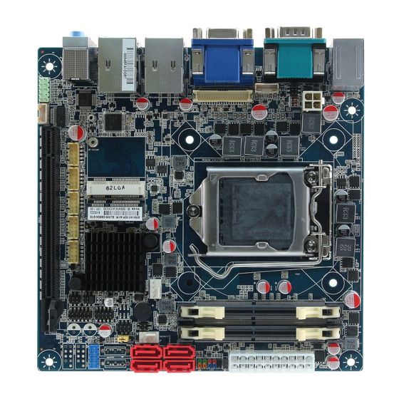
Page 16: Product Overview
EMX-H110KP-B1 User’s Manual 2.1 Product Overview 16 EMX-H110KP-B1 User’s Manual... -
Page 17: Jumper And Connector List
System fan connector Front panel setting connector 5 x 2 header, pitch 2.54 mm JFP1 260-pin DDR4 DIMM socket SODIMM1/2 Line out, Mic in, Line out AUDIO1 Front Audio connector 5 x 2 header, pitch 2.54 mm JAUDIO2 EMX-H110KP-B1 User’s Manual 17... - Page 18 Half size Mini-PCI-e connector 2 ATX Power connector 10 x 2 wafer, pitch 4.20mm ATXPWR1 ATX12V1 ATX 12V power connector 2 x 2 wafer, pitch 4.20mm Serial ATA III connector 4~6 SATA4~6 HDMI connector HDMI1 DP connector VGA1 VGA connector 18 EMX-H110KP-B1 User’s Manual...
-
Page 19: Setting Jumpers & Connectors
2.3 Setting Jumpers & Connectors 2.3.1 Serial port 1 pin9 signal select (JRI1) Ring* +12V * Default Note: Max Current 1A. 2.3.2 Serial port 2 pin9 signal select (JRI2) Ring* +12V * Default Note: Max Current 1A. EMX-H110KP-B1 User’s Manual 19... -
Page 20: At/Atx Power Mode Select (Jatatx1)
EMX-H110KP-B1 User’s Manual 2.3.3 AT/ATX Power Mode Select (JATATX1) ATX* * Default 2.3.4 Clear CMOS (JCMOS1) Protect* Clear CMOS * Default 20 EMX-H110KP-B1 User’s Manual... -
Page 21: Lcd Inverter Connector (Jbkl1)
User’s Manual 2.3.5 LCD Inverter connector (JBKL1) Signal Max current +12V BKLEN VBRIGHT Note: Mapping connector PHR5. 2.3.6 Serial port 2 connector (JCOM2) Signal PIN PIN Signal NRXDB NDCDB# NDTRB# NTXDB NDSRB# NCTSB# NRTSB# NRIB# EMX-H110KP-B1 User’s Manual 21... -
Page 22: Serial Port 3 Connector (Jcom3)
2.3.7 Serial port 3 connector (JCOM3) Signal PIN PIN Signal NRXDC NDCDC# NDTRC# NTXDC NDSRC# NCTSC# NRTSC# NRIC# 2.3.8 Serial port 4 connector (JCOM4) Signal PIN PIN Signal NRXDD NDCDD# NDTRD# NTXDD NDSRD# NCTSD# NRTSD# NRID# 22 EMX-H110KP-B1 User’s Manual... -
Page 23: Serial Port 5 Connector (Jcom5)
2.3.9 Serial port 5 connector (JCOM5) Signal PIN PIN Signal NRXDE NDCDE# NDTRE# NTXDE NDSRE# NCTSE# NRTSE# NRIE# 2.3.10 Serial port 6 connector (JCOM6) Signal PIN PIN Signal NRXDF NDCDF# NDTRF# NTXDF NDSRF# NCTSF# NRTSF# NRIF# EMX-H110KP-B1 User’s Manual 23... -
Page 24: Com2 Rs485/422 Connector (Jcom2_422_485)
EMX-H110KP-B1 User’s Manual 2.3.11 COM2 RS485/422 connector (JCOM2_422_485) Signal PIN PIN Signal 485_422TX- 422RX- 485_422TX+ 422RX+ Note: Max Current 1A. 2.3.12 General purpose I/O connector (JDIO1) Signal PIN PIN Signal SMB_CLK_9555_R 10 SMB_DATA_9555_R Note: Max Current 1A. +V5S_DIO 24 EMX-H110KP-B1 User’s Manual... -
Page 25: Atx Power Connector (Atxpwr1)
User’s Manual 2.3.13 ATX Power connector (ATXPWR1) Signal Signal +3.3V +3.3V -12V +3.3V PSON# PG_ATX +V5SB_DP +12V 2.3.14 USB 2.0 connector 1 (JUSB1) Signal Signal USB_R_DP6 USB_R_DP5 USB_R_DN6 USB_R_DN5 USBVCC_56 USBVCC_56 EMX-H110KP-B1 User’s Manual 25... -
Page 26: Battery Connector (Jbat1)
EMX-H110KP-B1 User’s Manual 2.3.15 Battery connector (JBAT1) Signal RTC_VBAT_1 2.3.16 ATX 12V power connector (ATX12V1) Signal Signal +V12S_4P +V12S_4P 26 EMX-H110KP-B1 User’s Manual... -
Page 27: Lvds Connector (Jlvds1)
LVDS_DATA2_P 16 15 LVDS_DATA3_P LVDS_DATA2_N 18 17 LVDS_DATA3_N Note: Mapping connector DF13-40DS-1.25C (1.0mm). LVDS_DATA4_P 22 21 LVDS_DATA5_P LVDS_DATA4_N 24 23 LVDS_DATA5_N LVDS_DATA6_P 28 27 LVDS_DATA7_P LVDS_DATA6_N 30 29 LVDS_DATA7_N LVDS_CLK1_P LVDS_CLK2_P LVDS_ CLK1_N LVDS_ CLK2_N +V12S_LVDS +V12S_LVDS EMX-H110KP-B1 User’s Manual 27... -
Page 28: Front Audio Connector (Jaudio2)
2.3.18.1 Signal Description –Audio connector 2 (JAUDIO2) Signal Signal Description LINE2_JD AUDIO IN (LINE_RIN/LIN)sense pin MIC2_JD MIC IN (MIC_RIN/LIN) sense pin 2.3.19 LPC connector (JLPC1) Signal PIN PIN Signal LPC_AD0 +3.3V LPC_AD1 BUF_PLT_RST# LPC_AD2 LPC_FRAME# LPC_AD3 LPC_CLK LPC_SERIRQ 28 EMX-H110KP-B1 User’s Manual... -
Page 29: Spi Connector (Jspi1)
User’s Manual 2.3.20 SPI connector (JSPI1) Signal PIN PIN Signal +V3.3_SPI SSPI_CS0#_R SSPI_SCLK_R SSPI_SO_R SSPI_SI_R SSPI_HOLD#0 2.3.21 Amplifier connector (JSPK1) Signal SPK_L+ SPK_L- SPK_R+ SPK_R- Note: Support 6W x 2 speakers. Mapping Connector PHR-4. EMX-H110KP-B1 User’s Manual 29... -
Page 30: Front Panel Setting Connector (Jfp1)
EMX-H110KP-B1 User’s Manual 2.3.22 Front panel setting connector (JFP1) Signal PIN PIN Signal +HD_LED +PWR_LED -HD_LED -PWE_LED +Reset +PWR_BNT -Reset -PWR_BNT 2.3.23 LAN1& LAN 2 active LED connector (JLANLED1) Signal PIN PIN Signal LAN2_ACT# LAN1_ACT# FRONT_LAN2_ACT FRONT_LAN1_ACT 30 EMX-H110KP-B1 User’s Manual... -
Page 31: Cpu Fan Connector (Cpufan1)
User’s Manual 2.3.24 CPU fan connector (CPUFAN1) Signal +12V CPUFANIN CPUFANOUT 2.3.25 System fan connector (SYSFAN1) Signal +12V SYSFANIN SYSFANOUT EMX-H110KP-B1 User’s Manual 31... -
Page 32: Gigabit Lan (Rj-45) Connector (Lan1/2)
Linked Green connection Note: 1Gbps This port allows Gigabit connection to a Local Area Blinking Data activity Orange connection Network (LAN) through a network hub. Refer to the table below for the LAN port LED indications. 32 EMX-H110KP-B1 User’s Manual... -
Page 33: Bios Setup
User’s Manual 3.BIOS Setup EMX-H110KP-B1 User’s Manual 33... -
Page 34: Introduction
If you do not press the keys at the correct time and the system does not boot, an error message will be displayed and you will again be asked to. Press F1 to Continue, DEL to enter SETUP 34 EMX-H110KP-B1 User’s Manual... -
Page 35: Using Setup
Note: Some of the navigation keys differ from one screen to another. To Display a Sub Menu Use the arrow keys to move the cursor to the sub menu you want. Then press <Enter>. A “” pointer marks all sub menus. EMX-H110KP-B1 User’s Manual 35... -
Page 36: Getting Help
BIOS Vendor and your systems manufacturer to provide the absolute maximum performance and reliability. Even a seemingly small change to the chipset setup has the potential for causing you to use the override. 36 EMX-H110KP-B1 User’s Manual... -
Page 37: Bios Setup
<Enter> to accept and enter the sub-menu. 3.6.1 Main Menu This section allows you to record some basic hardware configurations in your computer and set the system clock. EMX-H110KP-B1 User’s Manual 37... -
Page 38: System Language
Visit the Avalue website (www.avalue.com.tw) to download the latest product and BIOS information. 3.6.2 Advanced Menu This section allows you to configure your CPU and other system devices for basic operation through the following sub-menus. 38 EMX-H110KP-B1 User’s Manual... -
Page 39: Intel Rc Acpi Settings
User’s Manual 3.6.2.1 Intel RC ACPI Settings Item Options Description Auto [Default], Enabled – OS Controlled ASPM, Disabled – Native ASPM Enabled BIOS Controlled ASPM Disabled 3.6.2.2 CPU Configuration EMX-H110KP-B1 User’s Manual 39... -
Page 40: Cpu - Power Management Control
Enable/Disable C1E. When enabled, CPU will switch Enhanced C-states Enabled[Default] to minimum speed when all cores enter C-State. Disabled C-State Auto Demotion Configure C-State Auto Demotion C1 and C3[Default] Disabled C-State Un-demotion Configure C-State Un-demotion C1 and C3[Default] 40 EMX-H110KP-B1 User’s Manual... -
Page 41: View/Configure Turbo Options
Disable; 1: Enable; 2:Auto(Auto: Enabled for Skylake; Demotion Auto[Default] Disabled for Kabylake) Disabled, Enable or Disable Package C-State UnDemotion. 0: Package C-State Enabled Disable; 1: Enable; 2:Auto(Auto: Enabled for Skylake; Un-demotion Auto[Default] Disabled for Kabylake) 3.6.2.2.1.1 View/Configure Turbo Options 3.6.2.3 PCH-FW Configuration EMX-H110KP-B1 User’s Manual 41... -
Page 42: Firmware Update Configuration
When Disabled ME will be put into ME Temporarily ME State Enabled[Default] Disabled Mode. 3.6.2.3.1 Firmware Update Configuration Item Option Description Disabled[Default], Me FW Image Re-Flash Enable/Disable Me FW Image Re-Flash function. Enabled 3.6.2.4 Trusted Computing 42 EMX-H110KP-B1 User’s Manual... -
Page 43: Acpi Settings
Specify what state to go to when power is Pwr-On After PWR-Fail Always On re-applied after a power failure (G3 state). Keep Last state Disabled[Default], 30 sec 40 sec Watch Dog Select Watch Dog Timer (WDT) Mode. 50 sec 1 min 2 min EMX-H110KP-B1 User’s Manual 43... -
Page 44: S5 Rtc Wake Settings
Enable or disable System wake on RTC alarm Disabled[Default], event. Fixed Time: System will wake on the Wake system from S5 Fixed Time hr::min::sec specified. Dynamic_Time: System will Dynamic Time wake on the current time + Increase minute(s) 44 EMX-H110KP-B1 User’s Manual... -
Page 45: Super Io Configuration
Set Parameters of Serial Port 3 (COMC). Serial Port 4 Configuration Set Parameters of Serial Port 4 (COMD). Serial Port 5 Configuration Set Parameters of Serial Port 5 (COME). Serial Port 6 Configuration Set Parameters of Serial Port 6 (COMF). EMX-H110KP-B1 User’s Manual 45... -
Page 46: Serial Port 1 Configuration
EMX-H110KP-B1 User’s Manual 3.6.2.7.1 Serial Port 1 Configuration Item Option Description Disabled Serial Port Enable or Disable Serial Port (COM). Enabled[Default], 3.6.2.7.2 Serial Port 2 Configuration 46 EMX-H110KP-B1 User’s Manual... -
Page 47: Serial Port 3 Configuration
Enable or Disable Serial Port (COM). Enabled[Default], RS232[Default] Set COM Port as RS232, RS422 or RS485 UART 232 422 485 RS422 mode. RS485 3.6.2.7.3 Serial Port 3 Configuration Item Option Description Disabled Serial Port Enable or Disable Serial Port (COM). Enabled[Default], EMX-H110KP-B1 User’s Manual 47... -
Page 48: Serial Port 4 Configuration
EMX-H110KP-B1 User’s Manual 3.6.2.7.4 Serial Port 4 Configuration Item Option Description Disabled Serial Port Enable or Disable Serial Port (COM). Enabled[Default], 3.6.2.7.5 Serial Port 5 Configuration Item Option Description Serial Port Disabled Enable or Disable Serial Port (COM). 48 EMX-H110KP-B1 User’s Manual... -
Page 49: Serial Port 6 Configuration
User’s Manual Enabled[Default], 3.6.2.7.6 Serial Port 6 Configuration Item Option Description Disabled Serial Port Enable or Disable Serial Port (COM). Enabled[Default], 3.6.2.8 NCT6106D H/W Monitor EMX-H110KP-B1 User’s Manual 49... -
Page 50: Smart Fan Configuration
Smart Fan), SmartFan IV™ Mode. CPU Fan Manual Duty CPU Fan manual output duty: 0 to 255. Manual Smart Fan Mode Selection: Manual Mode (No SYSFAN1 Mode SmartFan IV[Default], Smart Fan), SmartFan IV™ Mode. 3.6.2.9 Serial Port Console Redirection 50 EMX-H110KP-B1 User’s Manual... -
Page 51: Legacy Console Redirection Settings
Console Redirection is disabled before booting to Always Enable[Default] legacy OS. When Always Enable is selected, then Redirect After POST BootLoader Legacy Console Redirection is enabled for legacy OS. Default setting for this option is set to Always Enable. EMX-H110KP-B1 User’s Manual 51... -
Page 52: Intel Txt Configuration
EMX-H110KP-B1 User’s Manual 3.6.2.10 Intel TXT Configuration 3.6.2.11 Network Stack Configuration Item Options Description Disabled[Default] Network Stack Enable/Disable UEFI Network Stack Enabled 52 EMX-H110KP-B1 User’s Manual... -
Page 53: Csm Configuration
User’s Manual 3.6.2.12 CSM Configuration Item Options Description Disabled[Default] CSM Support Enable/Disable CSM Support. Enabled 3.6.2.13 USB Configuration The USB Configuration menu helps read USB information and configures USB settings. EMX-H110KP-B1 User’s Manual 53... -
Page 54: Chipset
Floppy enumerates devices according to their media format. Optical drives are emulated as ‘CDROM’, Mass Storage Devices Forced FDD Hard Disk drives with no media will be emulated according to CD-ROM a drive type. 3.6.3 Chipset 54 EMX-H110KP-B1 User’s Manual... -
Page 55: System Agent (Sa) Configuration
User’s Manual 3.6.3.1 System Agent (SA) Configuration Item Option Description Disabled VT-d VT-d capability Enabled[Default] 3.6.3.1.1 Memory Configuration EMX-H110KP-B1 User’s Manual 55... -
Page 56: Graphics Configuration
1024x768 18/1 1366x768 18/1 1024x600 18/1 1280x800 18/1 CH7511 EDID Panel 1920x1200 24/2 Set which panel resolution EDID reported by Option 1920x1080 18/2 CH7511. 1280x1024 24/2 1440x900 18/2 1600x1200 24/2 1366x768 24/1 1920x1080 24/2 1680x1050 24/2 56 EMX-H110KP-B1 User’s Manual... -
Page 57: Dmi/Opi Configuration
User’s Manual 3.6.3.1.3 DMI/OPI Configuration 3.6.3.1.4 PEG Port Configuration Item Option Description Disabled Enable Root Port Enabled Enable or Disable the Root Port Auto[Default] Auto[Default] Max Link Speed Configure PEG 0:1:0 Max Speed Gen1 EMX-H110KP-B1 User’s Manual 57... -
Page 58: Peg Port Feature Configuration
Program PCIe ASPM Disabled[Default] after OpROM. Disabled: PCIe ASPM will be after OpROM Enabled programmed before OpROM. 3.6.3.1.4.1 PEG Port Feature Configuration Item Option Description Detect Disabled[Default] Detect Non-Compliance PCI Express Device Non-Compliance Enabled in PEG Device 58 EMX-H110KP-B1 User’s Manual... -
Page 59: Pch-Io Configuration
User’s Manual 3.6.3.2 PCH-IO Configuration Item Option Description Disabled Enable or disable OnBoard PCH LAN PHY LAN PHY Controller Enabled[Default] Controller. 3.6.3.2.1 PCI Express Configuration EMX-H110KP-B1 User’s Manual 59... -
Page 60: Intel I210 Lan Chip (Pci-E Port 8)
EMX-H110KP-B1 User’s Manual 3.6.3.2.1.1 Intel I210 LAN Chip (PCI-E Port 8) Item Option Description Intel I210 LAN Chip Disabled Control the PCI Express Root Port. (PCI-E Port 8) Enabled[Default] 3.6.3.2.1.2 Mini-PCIE Slot 2 (PCI-E Port 9) 60 EMX-H110KP-B1 User’s Manual... -
Page 61: Extra Options
3.6.3.2.1.2.1 Extra options Item Option Description Detect Disabled[Default] Detect Non-Compliance PCI Express Device. Non-Compliance Enabled If enable, it will take more time at POST time. Device Prefetchable Memory Range for this Root Prefetchable Memory Bridge. EMX-H110KP-B1 User’s Manual 61... -
Page 62: Mpcie1/Msata Slot (Pci-E Port 10)
PCIe Speed Gen1 Configure PCIe Speed Gen2 The number of milliseconds reference code will wait for link to exit Detect state for Detect Timeout enabled ports before assuming there is no device and potentially disabling the port. 62 EMX-H110KP-B1 User’s Manual... -
Page 63: Extra Options
If enable, it will take more time at POST time. Device Prefetchable Memory Range for this Root Prefetchable Memory Bridge. Reseved Memory Reseved Memory Alignment (0-31 bits) Alignment Prefetchable Memory Prefetchable Memory Alignment (0-31 bits) Alignment EMX-H110KP-B1 User’s Manual 63... -
Page 64: Sata And Rst Configuration
Gen3 Disabled SATA Port Enable or Disable SATA Port. Enabled[Default], Hard Disk Drive[Default] Identify the SATA port is connected to Solid SATA Device Type Solid State Drive State Drive or Hard Disk Drive. 64 EMX-H110KP-B1 User’s Manual... -
Page 65: Hd Audio Configuration
HDA will be unconditionally disabled Enabled = HDA HD Audio Enabled, will be unconditionally enabled Auto = HDA will be Auto[Default] enabled if present, disabled otherwise. 20 dB 26 dB[Default], Amplifier Gain Select Amplifier Gain(dB). 32 dB 36 dB EMX-H110KP-B1 User’s Manual 65... -
Page 66: Security
EMX-H110KP-B1 User’s Manual 3.6.4 Security Administrator Password Set setup Administrator Password User Password Set User Password 3.6.4.1 Secure Boot 66 EMX-H110KP-B1 User’s Manual... -
Page 67: Key Management
Custom mode Secure Boot Variables can be Custom[Default] configured without authentication 3.6.4.1.1 Key Management Item Option Description Provision Factory Disabled[Default] Allow to provision factory default Secure Boot Defaults Enabled, keys when System is in Setup Mode EMX-H110KP-B1 User’s Manual 67... -
Page 68: Boot
Enables or disables boot with initialization of a Disabled[Default] Fast Boot minimal set of devices required to launch active Enabled boot option. Has no effect for BBS boot options. Boot Option #1 #2 Set the system boot order. 68 EMX-H110KP-B1 User’s Manual... -
Page 69: Save And Exit
Reset the system after saving the changes. 3.6.6.2 Discard Changes and Reset Any changes made to BIOS settings during this session of the BIOS setup program are discarded. The setup program then exits and reboots the controller. EMX-H110KP-B1 User’s Manual 69... -
Page 70: Restore Defaults
This option restores all BIOS settings to the factory default. This option is useful if the controller exhibits unpredictable behavior due to an incorrect or inappropriate BIOS setting. 3.6.6.4 Launch EFI Shell from filesystem device Attempts to Launch EFI Shell application (Shellx64.efi) from one of the available filesystem devices. 70 EMX-H110KP-B1 User’s Manual... -
Page 71: Drivers Installation
User’s Manual 4. Drivers Installation Note: Installation procedures and screen shots in this section are for your reference and may not be exactly the same as shown on your screen. EMX-H110KP-B1 User’s Manual 71... -
Page 72: Install Chipset Driver
Official Website: http://www.avalue.com.tw. Note: The installation procedures and screen shots in this section are based on Windows 10 operation system. Step 3. Click Install. Step1. Click Next. Step 4. Step 2. Click Accept. Step 5. Complete setup. 72 EMX-H110KP-B1 User’s Manual... -
Page 73: Install Vga Driver
Windows 10 operation system. Step 3. Click Next. Step 1. Click Next to continue installation. Step 4. Click Next. Step 2. Step 5. Click Finish to complete setup. Click Yes to accept license agreement. EMX-H110KP-B1 User’s Manual 73... -
Page 74: Install Sol Driver
Windows 10 operation system. Step 3. Click Next Step 4. Step 1. Click Next to continue setup. Step 5. Click Finish to complete the setup Step 2. Click Next. 74 EMX-H110KP-B1 User’s Manual... -
Page 75: Install Audio Driver (For Realtek Alc888S Hd Audio)
All drivers can be found on the Avalue Official Website: http://www.avalue.com.tw. Note: The installation procedures and screen shots in this section are based on Windows 10 operation system. Step1. Click Next to Install. Step 3. Select Finish to complete Installation. Step 2. EMX-H110KP-B1 User’s Manual 75... -
Page 76: Install Lan Driver
Note: The installation procedures and screen shots in this section are based on Windows 10 operation system. Step 3. Click Next. Step 1. Click Install Drivers and Step 4. Click Next. Software. Step 2. Click Next. Step 5. Click Install. 76 EMX-H110KP-B1 User’s Manual... - Page 77 User’s Manual Step 6. Click Install. Step 7. Click Finish to complete setup. EMX-H110KP-B1 User’s Manual 77...
-
Page 78: Mechanical Drawing
EMX-H110KP-B1 User’s Manual 5. Mechanical Drawing 78 EMX-H110KP-B1 User’s Manual... - Page 79 User’s Manual Unit: mm Unit: mm EMX-H110KP-B1 User’s Manual 79...
Need help?
Do you have a question about the EMX-H110KP-B1 and is the answer not in the manual?
Questions and answers