Advertisement
Quick Links
EMS-CDV
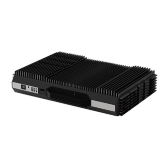
Fanless Intel® Atom™ D2550 Rugged Embedded
System with Intel® NM10 Express Chipset
Quick Reference Guide
st
Ed –27 November 2012
1
Copyright Notice
Copyright 2012 Avalue Technology Inc., ALL RIGHTS RESERVED.
Part No. E20178201A0R
This datasheet has been downloaded from
http://www.digchip.com
at this
page
Advertisement

Related Manuals for Avalue Technology EMS-CDV


Summary of Contents for Avalue Technology EMS-CDV
- Page 1 Fanless Intel® Atom™ D2550 Rugged Embedded System with Intel® NM10 Express Chipset Quick Reference Guide Ed –27 November 2012 Copyright Notice Copyright 2012 Avalue Technology Inc., ALL RIGHTS RESERVED. Part No. E20178201A0R This datasheet has been downloaded from http://www.digchip.com at this...
-
Page 2: Fcc Statement
Disclaimer Avalue Technology Inc. reserves the right to make changes, without notice, to any product, including circuits and/or software described or contained in this manual in order to improve design and/or performance. Avalue Technology assumes no responsibility or liability for the... -
Page 3: Getting Started
Place all electronic components in a static-dissipative surface or static-shielded bag when they are not in the chassis. 1.2 Packing List 1 x EMS-CDV Fanless Intel® Atom™ D2550 Rugged Embedded System with Intel® NM10 Express Chipset 1 x Quick Reference Guide ... -
Page 4: System Specifications
1 x Multi-Function Port for the following I/Os: Connector COM2 supports RS-232/422/485 selected by BIOS PS/2 for KB and MS SMBus 12-Bit GPIO Line-In, Line-Out, Mic-In 2 x Knockouts for Antenna Mounting PCIe Switch 4 EMS-CDV Quick Reference Guide... - Page 5 With mSATA/ SDD : 50G, IEC 60068-2-27, Half Sine, 11ms Shock Protection Certification CE, FCC Class B Dimension (W x H x D) 240mm x 170mm x 45mm Weight 4.4 lbs (2 Kgs) EMS-CDV Quick Reference Guide...
- Page 6 EMS-CDV 1.4 System Overview 1.4.1 Front & Top View EMS-CDV-255-A1-1R 6 EMS-CDV Quick Reference Guide...
- Page 7 Quick Reference Guide EMS-CDV-255-A1-2R/3R 1.4.2 Front View EMS-CDV Quick Reference Guide...
- Page 8 EMS-CDV 1.4.3 Rear View EMS-CDV-255-A1-1R EMS-CDV-255-A1-2R EMS-CDV-255-A1-3R 8 EMS-CDV Quick Reference Guide...
- Page 9 Serial port connector1 DC-IN DC power-in connector LAN1~5 RJ-45 Ethernet 1~5 Multi-Function Port combined COM2, Multi-function port 2 PS/2, Audio, GPIO and SMBus USB1~5 USB connector 1~5 VGA connector 2.5” Driver Bay and SIM Card Swappable Drawer EMS-CDV Quick Reference Guide...
-
Page 10: Jumper And Connector Setting, Driver And Bios Installing
Configuration Jumper and Connector Setting, Driver and BIOS Installing For advanced information, please refer to: 1- EBM-CDVS, AUX-M01 and AUX-M02 included in this manual. Note: If you need more information, please visit our website: http://www.avalue.com.tw 10 EMS-CDV Quick Reference Guide... - Page 11 External Serial Port 1 connector (COM1) Signal PIN PIN Signal NDCDA#_485TXN NDSRA# NRXDA#_485TXP NRTSA# NTXDA#_485RXP NCTSA# NDTRA#_485RXN NRIA# 2.1.2 External Serial Port 3/4/5/6 connector (COM3/4/5/6) Signal PIN PIN Signal DCD1#_485TXN DSR1# RXD1_485TXP RTS1# TXD1_485RXP CTS1# DTR1#_485RXN RI1# EMS-CDV Quick Reference Guide 11...
- Page 12 Multi-Function Port combined COM2, 2 PS/2, Audio, GPIO and SMBus (Multi-function port) Signal Signal Signal LINE1_JD FRONT_JD LINE1_RIN MIC1_JD LINEOUT_R MIC_RIN LINE1_LIN LINEOUT_L MIC_LIN SMB_CLK MSCK SMB_DATA NRIB# NRTSB# MSDA NCTSB# COM2_GND KBDA NDSRB# NTXDB_485RXP 14 VCC_PS2 NDTRB#_485RXN NDCDB#_485TXN KBCK NRXDB_485TXP 12 EMS-CDV Quick Reference Guide...
- Page 13 Quick Reference Guide 2.1.4.1 GPIO+SMBUS Signal PIN PIN Signal SMBUS_DATA SMBUS_CLK GPI-D5 GPI-D4 GPO-D5 GPI-D3 GPO-D4 GPI-D2 GPO-D3 GPI-D1 GPO-D2 GPI-D0 GPO-D1 GPO-D0 2.1.4.2 COM2 Signal PIN PIN Signal EMS-CDV Quick Reference Guide 13...
- Page 14 EMS-CDV 2.2 EBM-CDVS,AUX-M01 and AUX-M02 Overviews 2.2.1 EBM-CDVS 14 EMS-CDV Quick Reference Guide...
- Page 15 Quick Reference Guide 2.2.2 AUX-M01 2.2.3 AUX-M02 EMS-CDV Quick Reference Guide 15...
- Page 16 LCD backlight brightness adjustment 3 x 1 header, pitch 2.54 mm Front Panel Connector 1 5 x 1 wafer, pitch 2.00 mm Front Panel Connector 2 8 x 1 wafer, pitch 2.00 mm DCOUT_S DC Output connector 6 x 1 wafer, pitch 2.00 mm 16 EMS-CDV Quick Reference Guide...
- Page 17 Quick Reference Guide 2.4 EBM-CDVS Jumpers & Connectors settings 2.4.1 Clear CMOS (CMOS1) Protect* Clear CMOS *Default 2.4.2 COM 1/2 pin 9 signal select (JRI1/2) Ring* +12V JRI1 JRI2 * Default EMS-CDV Quick Reference Guide 17...
- Page 18 EMS-CDV 2.4.3 LPC port connector (LPC1) Signal Signal LPC_AD0 LPC_AD1 PLTRST# LPC_AD2 LPC_LFRAME# LPC_AD3 LPC1_PCI_CLK SERIRQ LPC_LDRQ1# 2.4.4 Power connector (PWR1) Signal +12V 18 EMS-CDV Quick Reference Guide...
- Page 19 Quick Reference Guide 2.4.5 LCD inverter connector (BKL1) Signal +12V LVDS_BKLTEN BRIGHT 2.4.6 LCD backlight brightness adjustment (JVR) Signal BRIGHT Variation Resistor (Recommended: 4.7KΩ, >1/16W) EMS-CDV Quick Reference Guide 19...
- Page 20 EMS-CDV 2.4.7 SPI connector (SPI1) Signal Signal SPI_CS# SPI_CLK SPI_SO SPI_SI SPI_HOLD# 2.4.8 Front Panel Connector 1 (CN1) Signal PWRBTN# RESET# POWER LED+ POWER LED- 20 EMS-CDV Quick Reference Guide...
- Page 21 Quick Reference Guide 2.4.9 Front Panel Connector 2 (CN2) Signal SATA_LED+ SATA_LED- LAN ACT LED+ LAN ACT LED- LAN LINK100+ LAN LINK100- LAN LINK1000+ LAN LINK1000- 2.4.10 DC Output connector (DCOUT_S) Signal DCIN DCIN DCIN EMS-CDV Quick Reference Guide 21...
- Page 22 USB connector 2~3 LAN2~5 LAN connector 2~5 JLAN23 LAN2/3 ACT/LNK/SPD LED 8 x 1 wafer, pitch 2.00mm JLAN45 LAN4/5 ACT/LNK/SPD LED 8 x 1 wafer, pitch 2.00mm Normal/Bypass mode LED 8 x 1 wafer, pitch 2.00mm JLANMODE 22 EMS-CDV Quick Reference Guide...
- Page 23 Quick Reference Guide 2.6 AUX-M01 Jumpers & Connectors settings 2.6.1 COM 3/4/5/6 pin 9 signal select (JRI3/4/5/6) JRI6 Ring* JRI5 +12V JRI4 JRI3 * Default 2.6.2 USB connector (USB3) Signal PUSBP3 PUSBN3 PV5A_USB3 EMS-CDV Quick Reference Guide 23...
- Page 24 EMS-CDV 2.6.3 USB connector (JUSB3) Signal PUSBP3 PUSBN3 PV5A_USB3 24 EMS-CDV Quick Reference Guide...
- Page 25 Quick Reference Guide 2.7 AUX-M02 Jumpers & Connectors settings 2.7.1 LAN4/5 ACT/LNK/SPD LED (JLAN45) Signal LAN5_ACT_LED+ LAN5_ACT_LED- LAN5_LINK100 LAN5_LINK1000 LAN4_ACT_LED+ LAN4_ACT_LED- LAN4_LINK100 LAN4_LINK1000 2.7.2 LAN2/3 ACT/LNK/SPD LED (JLAN23) Signal LAN3_ACT_LED+ LAN3_ACT_LED- LAN3_LINK100 LAN3_LINK1000 LAN2_ACT_LED+ LAN2_ACT_LED- LAN2_LINK100 LAN2_LINK1000 EMS-CDV Quick Reference Guide 25...
- Page 26 EMS-CDV 2.7.3 Normal/Bypass mode LED (JLANMODE) Signal LAN23_Normal_state_LED+ LAN23_Normal_state_LED- LAN23_Bypass_state_LED+ LAN23_Bypass_state_LED- LAN45_Normal_state_LED+ LAN45_Normal_state_LED- LAN45_Bypass_state_LED+ LAN45_Bypass_state_LED- 26 EMS-CDV Quick Reference Guide...
- Page 27 Quick Reference Guide 2.8 Installing Hard Disk & Memory, PCI devices (EMS-CDV) Step 1. Remove 6 screws from the bottom of your system. Step 2. Remove the chassis cover. Step 1. Remove 5 screws to release the HDD bracket. Step 2.1. Slide HDD into its bracket until properly seated.
- Page 28 EMS-CDV 2.9 Installing Mounting Brackets (EMS-CDV) Step 1. Position brackets on both sides, matching the holes on the system. Step 2. Insert and fasten screw on each side of the system to secure Mounting brackets. 28 EMS-CDV Quick Reference Guide...
Need help?
Do you have a question about the EMS-CDV and is the answer not in the manual?
Questions and answers