Table of Contents

Related Manuals for Avalue Technology EMS-EHL


Summary of Contents for Avalue Technology EMS-EHL
- Page 1 EMS-EHL Intel® Atom™ / Celeron Elkhart Lake Fanless Embedded Moduler System Quick Reference Guide Ed –07 February 2023 Copyright Notice Copyright 2023 Avalue Technology Inc., ALL RIGHTS RESERVED. Part No. E2017AAQ0A0R...
- Page 2 These answers are normally a lot more detailed than the ones we can give over the phone. So please consult the user’s manual first. To receive the latest version of the user’s manual; please visit our Web site at: http://www.avalue.com.tw/ 2 EMS-EHL Quick Reference Guide...
-
Page 3: Table Of Contents
Power on/off connector (PWRBTN1) ..................32 2.4.13 IET connector (IET_CB1) ...................... 33 2.4.14 Battery connector (BATH2) ....................34 Installing Hard Disk & Memory (EMS-EHL) ............35 3.BIOS Setup ........................36 Introduction ......................37 Starting Setup ...................... 37 Using Setup ......................38... - Page 4 Driver Health ........................58 3.6.3 Chipset ............................59 3.6.3.1 System Agent (SA) Configuration ..................59 3.6.3.1.1 Memory Configuration ....................... 60 3.6.3.1.2 Graphics Configuration...................... 60 3.6.3.2 PCH-IO Configuration ......................61 3.6.3.2.1 PCI Express Configuration ....................61 4 EMS-EHL Quick Reference Guide...
- Page 5 Restore Defaults ........................ 73 4. Drivers Installation ....................... 74 Install Chipset Driver ................... 75 Install ME Driver ....................76 Install VGA Driver ....................77 Install Audio Driver (For Realtek ALC888S) ............78 Install Ethernet Driver ..................79 EMS-EHL Quick Reference Guide...
-
Page 6: Getting Started
1.2 Packing List 1 x EMS-EHL Intel® Celeron® / Atom® SoC Processor J6413/x6425E Fanless Rugged Embedded System 1 x Terminal block to lockable DC Jack cable ... -
Page 7: System Specifications
EBM-EHLS +IET-BYPASS (EMS-EHL-6 LAN Bypass) EBM-EHLS +IET-Normal LAN (EMS-EHL-6 LAN Normal) Board EBM-EHLS +IET-PSEBF (EMS-EHL-PSEBF), support 4 port IEEE 802.af EBM-EHLS +IET-PSEBT (EMS-EHL-PSEBT), support 2 port IEEE 802.at EBM-EHLS +AUX-M07 (EMS-EHL-4 COM Isolation) EBM-EHLS +EBM-BYTS DB-A (EMS-EHL-HDMI) ... - Page 8 2 x USB 3.1 Gen.2 (10Gbp/s) 2 x USB 3.1 Gen.1 (5Gbp/s), via USB Hub EMS-EHL-HDMI, EMS-EHL-DVI, EMS-EHL-6COM, EMS-EHL-4COM isolation, EMS-EHL-PSEBF, EMS-EHL-PSEBT, EMS-EHL-6 LAN Bypass, EMS-EHL 6 LAN Normal USB Port 2 x USB 3.1 Gen.2 (10Gbp/s) ...
- Page 9 Quick Reference Guide 6 x RJ45, 4 port Powered LAN support IEEE802.af EMS-EHL-6 LAN Bypass, EMS-EHL 6 LAN Normal 6 x RJ45 EMS-EHL-HDMI 2 x COM RS232/422/485 (select via BIOS, auto flow control via HW) EMS-EHL-6COM ...
- Page 10 240mm x 150mm x 43 mm (Standard) 240mm x 150mm x 64 mm (w/ IET module) Weight 1910 g Color Avalue Box PC family design Mounting Kit Wall mount kit (standard) 10 EMS-EHL Quick Reference Guide...
- Page 11 -30°C ~ 70°C (-22°F ~ 158°F) Temperature Certification CE, FCC Class B, LVD 62368-1 OS Supported Win 10 64bit / Win 11 64 bit/ Linux Compliant with following Flexible IET Expansion Modules (Optional) EMS-EHL Quick Reference Guide 11...
- Page 12 1 x HDMI, 2 x RJ45, 2 x RS-232/422/485 (BIOS), 2 x USB 2.0 AUX-M01 4 x RS-232/422/485(BIOS), 2 x USB 2.0 AUX-M07 4 x RS-232/422/485(BIOS) w/ 2.5KV isolation, 2 x USB 2.0 Note: Specifications are subject to change without notice. 12 EMS-EHL Quick Reference Guide...
-
Page 13: System Overview
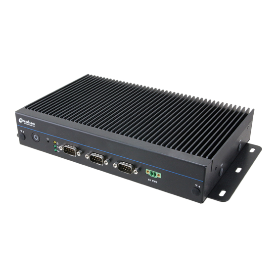
Quick Reference Guide 1.4 System Overview 1.4.1 Front View EMS-EHL EMS-EHL-6 COM/EMS-EHL-6 LAN Bypass/EMS-EHL-6 LAN Normal /EMS-EHL-PSEBF/EMS-EHL-PSEBT/EMS-EHL-4 COM Isolation /EMS-EHL-HDMI/EMS-EHL-DVI/EMS-EHL-USB 1.4.2 Rear View EMS-EHL EMS-EHL Quick Reference Guide 13... - Page 14 EMS-EHL EMS-EHL-6 COM/EMS-EHL-4 COM Isolation EMS-EHL-6 LAN Bypass/EMS-EHL-6 LAN Normal/EMS-EHL-PSEBF EMS-EHL-PSEBT 14 EMS-EHL Quick Reference Guide...
- Page 15 Quick Reference Guide EMS-EHL-HDMI EMS-EHL-DVI EMS-EHL-USB EMS-EHL Quick Reference Guide 15...
- Page 16 Serial port connector 1/2/3/4/5/6 GPIO General purpose I/O connector EX PWR Power on button Mic-in Mic-in audio jack Line-out Line-out jack HDMI HDMI connector DP connector USB 3.1 Gen.1 2 x USB 3.1 Gen.1 connector 16 EMS-EHL Quick Reference Guide...
- Page 17 USB 3.1 Gen.2 2 x USB 3.1 Gen.2 connector 2 x USB 2.0 connector USB 2.0 LAN1/2 RJ-45 Ethernet 1/2 DC-in DC power-in connector EMS-EHL-6 LAN Bypass/EMS-EHL-6 LAN Normal/EMS-EHL-PSEBF Connectors Label Function Note Power System power indicator Reset Reset button...
- Page 18 2 x USB 3.1 Gen.1 connector USB 3.1 Gen.2 2 x USB 3.1 Gen.2 connector USB 2.0 2 x USB 2.0 connector RJ-45 Ethernet 1/2/3/4 LAN1/2/3/4 DC-in DC power-in connector EMS-EHL-DVI Connectors Label Function Note System power indicator Power 18 EMS-EHL Quick Reference Guide...
- Page 19 Mic-in audio jack Line-out Line-out jack HDMI HDMI connector DP connector USB 3.1 Gen.1 6 x USB 3.1 Gen.1 connector 2 x USB 3.1 Gen.2 connector USB 3.1 Gen.2 USB 2.0 3 x USB 2.0 connector EMS-EHL Quick Reference Guide 19...
- Page 20 EMS-EHL LAN1/2 RJ-45 Ethernet 1/2 DC-in DC power-in connector 20 EMS-EHL Quick Reference Guide...
-
Page 21: System Dimensions
Quick Reference Guide 1.5 System Dimensions 1.5.1 Front & Top View (Unit: mm) EMS-EHL Quick Reference Guide 21... -
Page 22: Hardware Configuration
EMS-EHL 2. Hardware Configuration Jumper and Connector Setting, Driver and BIOS Installing For advanced information, please refer to: 1- EBM-EHLS included in this manual. Note: If you need more information, please visit our website: http://www.avalue.com.tw 22 EMS-EHL Quick Reference Guide... -
Page 23: Ems-Ehl Connector Mapping
Serial Port 1/2 connector (COM1/2) In RS-422 Mode Signal PIN PIN Signal In RS-232 Mode Signal Signal TxD1- NDCD# NDSR# TxD1+ NRXD NRTS# RxD1+ NTXD NCTS# RxD1- NDTR# NRI# In RS-485 Mode Signal PIN PIN Signal DATA1- DATA1+ EMS-EHL Quick Reference Guide 23... -
Page 24: Ebm-Ehls Overviews
EMS-EHL 2.2 EBM-EHLS Overviews 24 EMS-EHL Quick Reference Guide... -
Page 25: Ebm-Ehls Jumper & Connector List
IET connector BIOS_SPI1 BIOS SPI connector 4 x 2 header, pitch 2.00 mm JESPI1 eSPI connector 6 x 2 header, pitch 1.27 mm DP connector M.2 Key-B 2242/3042/3052 NGFF1 connector NGFF2 M.2 KEY-B 2242/2280 connector EMS-EHL Quick Reference Guide 25... - Page 26 6 x 1 wafer, pitch 2.50 mm JVIN1 DC Input connector 1 x 3 terminal block, pitch 5.08 mm EC Debug connector 5 x 2 header, pitch 2.00 mm JEC_ROM1 BATH2 Battery connector 2 x 1 wafer, pitch 1.25 mm 26 EMS-EHL Quick Reference Guide...
-
Page 27: Ebm-Ehls Jumpers & Connectors Settings
2.4 EBM-EHLS Jumpers & Connectors settings 2.4.1 Multi-function select (SW1) Power mode ATX* DDI2 mode(DP+) DisplayPort* HDMI Cable select N.C. WWAN 2.4.2 Serial port 1/2 pin 9 signal select (JRI1/2) JRI1 Ring* JRI2 +12V * Default EMS-EHL Quick Reference Guide 27... -
Page 28: Serial Port 1/2 Rs-232/422/485 Mode Select (Jcom_Sel1/2)
EMS-EHL 2.4.3 Serial port 1/2 RS-232/422/485 mode select (JCOM_SEL1/2) RS-232* JCOM_SEL1 JCOM_SEL2 RS-422/ 485 *Default 2.4.4 Clear CMOS (JBAT1) Protect * Clear CMOS *Default 28 EMS-EHL Quick Reference Guide... -
Page 29: Espi Connector (Jespi1)
Quick Reference Guide 2.4.5 eSPI connector (JESPI1) Signal Signal CN_ESPI_IO0 +3.3V CN_ESPI_IO1 PLT_RST1# CN_ESPI_IO2 ESPI_CS#0 CN_ESPI_IO3 CN_ESPI_CLK ESPI_RST ESPI_ALERT#2 2.4.6 BIOS SPI connector (BIOS_SPI) Signal Signal SPI_WP# SPI_HOLD# SPI_MOSI SPI_MISO SPI0 _CLK SPI_CS0# +3.3VSB EMS-EHL Quick Reference Guide 29... -
Page 30: Front Panel Connector (Jfp1)
EMS-EHL 2.4.7 Front Panel connector (JFP1) Signal PWR_LED- +5VSB PMC_RSTBTN# PWR_BTN_IN_EC# 2.4.8 DC Output connector (DCOUT1) Signal +V36_VIN +V36_VIN +V36_VIN 30 EMS-EHL Quick Reference Guide... -
Page 31: Dc Input Connector (Jvin1)
Quick Reference Guide 2.4.9 DC Input connector (JVIN1) Signal +DC_IN CHASSIS_GND 2.4.10 EC Debug connector (JEC_ROM1) Signal Signal +VSPI_EC EC_FSCE# EC_FSCK EC_FMISO EC_FMOSI EC_HOLD# EC_SMCLK_DBG EC_SMDAT_DBG EMS-EHL Quick Reference Guide 31... -
Page 32: On-Board Header For Usb2.0 (Jusb1)
EMS-EHL 2.4.11 On-board header for USB2.0 (JUSB1) Signal Signal +5VSB +5VSB USB_R_DN3 USB_R_DN4 USB_R_DP3 USB_R_DP4 2.4.12 Power on/off connector (PWRBTN1) Signal PWRBTN#_R 32 EMS-EHL Quick Reference Guide... -
Page 33: Iet Connector (Iet_Cb1)
Signal Signal DDI0_AUXP_DAT LPC_LDRQ# LPC_SERIRQ PCIE_SW1_RXP_1 PCIE_SW1_TXP_1 DDI0_C_TXP0 LPC_LFRAME# PCIE_SW1_RXN_1 PCIE_SW1_TXN_1 DDI0_C_TXN0 USB_DP_7 PCIE_SW1_RXP_2 PCIE_SW1_TXP_2 DDI0_C_TXP1 USB_DN_7 PCIE_SW1_RXN_2 PCIE_SW1_TXN_2 DDI0_C_TXN1 USB_DP_8 PCIE_SW2_RXP_1 PCIE_SW2_TXP_1 DDI0_C_TXP2 USB_DN_8 PCIE_SW2_RXN_1 PCIE_SW2_TXN_1 DDI0_C_TXN2 USB_DP_9 DDI0_C_TXP3 USB_DN_9 DDI0_C_TXN3 USB2_OC3# +12VSB +12VSB EMS-EHL Quick Reference Guide 33... -
Page 34: Battery Connector (Bath2)
EMS-EHL 2.4.14 Battery connector (BATH2) Signal PWRBTN#_R 34 EMS-EHL Quick Reference Guide... -
Page 35: Installing Hard Disk & Memory (Ems-Ehl)
Quick Reference Guide 2.5 Installing Hard Disk & Memory (EMS-EHL) Step 1. Remove 8 screws from the bottom of your system and take it off. Step 2. Slide the DDR4 SODIMM into the memory socket and press it down until properly seated. -
Page 36: Bios Setup
EMS-EHL 3.BIOS Setup 36 EMS-EHL Quick Reference Guide... -
Page 37: Introduction
If you do not press the keys at the correct time and the system does not boot, an error message will be displayed and you will again be asked to. Press F1 to Continue, DEL to enter SETUP EMS-EHL Quick Reference Guide 37... -
Page 38: Using Setup
Note: Some of the navigation keys differ from one screen to another. To Display a Sub Menu Use the arrow keys to move the cursor to the sub menu you want. Then press <Enter>. A “” pointer marks all sub menus. 38 EMS-EHL Quick Reference Guide... -
Page 39: Getting Help
BIOS Vendor and your systems manufacturer to provide the absolute maximum performance and reliability. Even a seemingly small change to the chipset setup has the potential for causing you to use the override. EMS-EHL Quick Reference Guide 39... -
Page 40: Bios Setup
<Enter> to accept and enter the sub-menu. 3.6.1 Main Menu This section allows you to record some basic hardware configurations in your computer and set the system clock. 40 EMS-EHL Quick Reference Guide... -
Page 41: System Language
Visit the Avalue website (www.avalue.com.tw) to download the latest product and BIOS information. 3.6.2 Advanced Menu This section allows you to configure your CPU and other system devices for basic operation through the following sub-menus. EMS-EHL Quick Reference Guide 41... -
Page 42: Cpu Configuration
Item Options Description When enabled, a VMM can utilize the additional Intel(VMX) Virtualization Disabled hardware capabilities provided by Vanderpool Technology Enabled[Default] Technology. All[Default] Number of cores to enable in each processor Active Processor Cores package. 42 EMS-EHL Quick Reference Guide... -
Page 43: Power & Performance
Allows more than two frequency ranges to be Intel® SpeedSted™ Enabled[Default], supported. Enable/Disable Intel® Speed Shift Technology Intel® Speed Shift Disabled[Default], support. Enabling will expose the CPPC v2 Technology Enabled interface to allow for hardware controlled EMS-EHL Quick Reference Guide 43... -
Page 44: View/Configure Turbo Options
Allows CPU to go to C states when it’s not 100% C states Enabled utilized. 3.6.2.2.1.1 View/Configure Turbo Options 3.6.2.2.2 GT - Power Management Control Item Option Description RC6(Render Standby) Disabled Check to enable render standby support. 44 EMS-EHL Quick Reference Guide... -
Page 45: Pch-Fw Configuration
Enabled: Disables Turbo GT frequency. frequency Enabled Disabled: GT frequency is not limited 3.6.2.3 PCH-FW Configuration 3.6.2.3.1 Firmware Update Configuration Item Option Description Disabled[Default], Me FW Image Re-Flash Enable/Disable Me FW Image Re-Flash function. Enabled EMS-EHL Quick Reference Guide 45... -
Page 46: Ptt Configuration
Selects TPM device: PTT or dTPM. PTT - dTPM[Default], Enables PTT in SkuMgr dTPM 1.2 - Disables TPM Device Selection PTT in SkuMgr Warning ! PTT/dTPM will be disabled and all data saved on it will be lost. 3.6.2.4 Trusted Computing 46 EMS-EHL Quick Reference Guide... -
Page 47: Acpi Settings
SUSPEND button is pressed. [Default] 3.6.2.6 IT5571 Super IO Configuration You can use this item to set up or change the IT8528 Super IO configuration for serial ports. Please refer to 3.6.2.6.1~ 3.6.2.6.6 for more information. EMS-EHL Quick Reference Guide 47... - Page 48 Set Parameters of Serial Port 3 (COMC). Serial Port 4 Configuration Set Parameters of Serial Port 4 (COMD). Serial Port 5 Configuration Set Parameters of Serial Port 5 (COME). Serial Port 6 Configuration Set Parameters of Serial Port 5 (COMF). 48 EMS-EHL Quick Reference Guide...
-
Page 49: Serial Port 1 Configuration
3.6.2.6.1 Serial Port 1 Configuration Item Option Description Disabled Serial Port Enable or Disable Serial Port (COM). Enabled[Default], UART 232[Default] UART 232 422 485 UART 422 Change the Serial Port as RS232/422/485. UART 485 3.6.2.6.2 Serial Port 2 Configuration EMS-EHL Quick Reference Guide 49... -
Page 50: Serial Port 3 Configuration
UART 232 422 485 Change the Serial Port as RS232/422/485. UART 422 UART 485 Disabled[Default], Adjust the Serial Port with internal or external 422/485 termination Enabled termination resistors 10M bps Slew limiting SLEW from GPIO. 250k bps[Default] 50 EMS-EHL Quick Reference Guide... -
Page 51: Serial Port 4 Configuration
UART 232 422 485 Change the Serial Port as RS232/422/485. UART 422 UART 485 Disabled[Default], Adjust the Serial Port with internal or external 422/485 termination Enabled termination resistors 10M bps Slew limiting SLEW from GPIO. 250k bps[Default] EMS-EHL Quick Reference Guide 51... -
Page 52: Serial Port 5 Configuration
UART 232 422 485 Change the Serial Port as RS232/422/485. UART 422 UART 485 Disabled[Default], Adjust the Serial Port with internal or external 422/485 termination Enabled termination resistors 10M bps Slew limiting SLEW from GPIO. 250k bps[Default] 52 EMS-EHL Quick Reference Guide... -
Page 53: Serial Port 6 Configuration
UART 232 422 485 Change the Serial Port as RS232/422/485. UART 422 UART 485 Disabled[Default], Adjust the Serial Port with internal or external 422/485 termination Enabled termination resistors 10M bps Slew limiting SLEW from GPIO. 250k bps[Default] EMS-EHL Quick Reference Guide 53... -
Page 54: H/W Monitor
Enable or disable System wake on alarm event. Disabled[Default], Select Fixed Time, system will wake on the Wake system from S5 Fixed Time hr::min::sec specified. Select Dynamic Time, Dynamic Time System will wake on the current time + Increase minute(s). 54 EMS-EHL Quick Reference Guide... -
Page 55: Serial Port Console Redirection
Options Description Disabled[Default], Console Redirection Console Redirection Enable or Disable. Enabled Console Redirection Disabled[Default], Console Redirection Enable or Disable. Enabled 3.6.2.10 USB Configuration The USB Configuration menu helps read USB information and configures USB settings. EMS-EHL Quick Reference Guide 55... -
Page 56: Network Stack Configuration
Optical drives are emulated as ‘CDROM’, Forced FDD 1100 Hard Disk drives with no media will be emulated according CD-ROM to a drive type. 3.6.2.11 Network Stack Configuration Item Options Description Disabled[Default], Network Stack Enable/Disable UEFI Network Stack. Enabled 56 EMS-EHL Quick Reference Guide... -
Page 57: Nvme Configuration
Quick Reference Guide 3.6.2.12 NVMe Configuration 3.6.2.13 Intel® Ethernet Controller I226-IT – 00:04:5F:96:CF:22 EMS-EHL Quick Reference Guide 57... -
Page 58: Intel® Ethernet Controller I226-It - 00:04:5F:96:Cf:23
EMS-EHL 3.6.2.14 Intel® Ethernet Controller I226-IT – 00:04:5F:96:CF:23 3.6.2.15 Driver Health 58 EMS-EHL Quick Reference Guide... -
Page 59: Chipset
Quick Reference Guide 3.6.3 Chipset 3.6.3.1 System Agent (SA) Configuration Item Option Description Disabled VT-d VT-d capability. Enabled[Default] EMS-EHL Quick Reference Guide 59... -
Page 60: Memory Configuration
Select GTT Size 8MB[Default] 128MB Select the Aperture Size Note : Above 4GB 256MB[Default] MMIO BIOS assignment is automatically enabled Aperture Size 512MB when selecting 2048MB aperture. To use this 1024MB feature, please disable CSM Support. 60 EMS-EHL Quick Reference Guide... -
Page 61: Pch-Io Configuration
Quick Reference Guide 3.6.3.2 PCH-IO Configuration 3.6.3.2.1 PCI Express Configuration EMS-EHL Quick Reference Guide 61... -
Page 62: Pci Express Root Port 3(Lan1-I225/I226)
L0s State AUTO – BIOS auto configure ASPM DISABLE – Disables ASPM. L0sL1 Auto Disabled[Default], L1 Substates L1.1 PCI Express L1 Substates settings. L1.1 & L1.2 Disabled[Default], Enable/Disable Precision Time Measurement Enabled Auto[Default] Gen1 PCIe Speed Configure PCIe speed Gen2 Gen3 62 EMS-EHL Quick Reference Guide... -
Page 63: Pci Express Root Port 4(Lan2-I225/I226)
L0s State AUTO – BIOS auto configure ASPM DISABLE – Disables ASPM. L0sL1 Auto Disabled[Default], L1 Substates L1.1 PCI Express L1 Substates settings. L1.1 & L1.2 Disabled[Default], Enable/Disable Precision Time Measurement Enabled Auto[Default] Gen1 PCIe Speed Configure PCIe speed Gen2 Gen3 EMS-EHL Quick Reference Guide 63... -
Page 64: Pci Express Root Port 5(M.2 Keyb/Iet)
L0s State AUTO – BIOS auto configure ASPM DISABLE – Disables ASPM. L0sL1 Auto Disabled[Default], L1 Substates L1.1 PCI Express L1 Substates settings. L1.1 & L1.2 Disabled[Default], Enable/Disable Precision Time Measurement Enabled Auto[Default] Gen1 PCIe Speed Configure PCIe speed Gen2 Gen3 64 EMS-EHL Quick Reference Guide... -
Page 65: Pci Express Root Port 7(M.2 Keye/Iet)
ASPM configure DISABLE – Disables ASPM. L0sL1 Auto Disabled L1 Substates L1.1 PCI Express L1 Substates settings. L1.1 & L1.2[Default], Disabled[Default], Enable/Disable Precision Time Enabled Measurement Auto[Default] Gen1 PCIe Speed Configure PCIe speed. Gen2 Gen3 EMS-EHL Quick Reference Guide 65... -
Page 66: Sata Configuration
Enable or Disable SATA Port. Disabled, 3.6.3.2.3 USB Configuration Item Option Description Option to enable Compliance Mode. Default Disabled[Default] XHCI Compliance Mode is to disable Compliance Mode. Change to Enabled enabled for Compliance Mode testing. 66 EMS-EHL Quick Reference Guide... -
Page 67: Hd Audio Configuration
Control Detection of the HD-Audio device. Disabled Disable = HDA will be unconditionally HD Audio Enabled[Default], disabled Enabled = HDA will be unconditionally enabled. 3.6.3.2 Board & Panel Configuration Item Option Description Disabled[Default] ErP Function ErP Function (Deep S5). Enabled EMS-EHL Quick Reference Guide 67... -
Page 68: Security
30 min Disabled Enable/Disabled USB Standby Power USB Standby Power Enabled[Default] during S3/S4/S5. Disabled[Default] SHOW DMI INFO SHOW DMI INFO. Enabled 3.6.4 Security Administrator Password Set setup Administrator Password User Password Set User Password 68 EMS-EHL Quick Reference Guide... -
Page 69: Secure Boot
System is in User mode. The mode change requires platform reset. Secure Boot mode options: Standard or Custom. In Standard Custom mode, Secure Boot Policy variables can be Secure Boot Mode Custom[Default] configured by a physically present user without full authentication. EMS-EHL Quick Reference Guide 69... -
Page 70: Key Management
EMS-EHL 3.6.4.1.1 Key Management Item Option Description Install factory default Secure Boot keys after Disabled[Default] Factory Key Provision the platform reset and while the System is in Enabled Setup mode. 70 EMS-EHL Quick Reference Guide... -
Page 71: Boot
1~ 65535 activation key. 65535(0xFFFF) means indefinite waiting. On[Default] Bootup NumLock State Select the Keyboard NumLock state Disabled[Default] Quiet Boot Enables or disables Quiet Boot option Enabled Boot Option #1/2 Set the system boot order. EMS-EHL Quick Reference Guide 71... -
Page 72: Save And Exit
Reset the system after saving the changes. 3.6.6.2 Discard Changes and Reset Any changes made to BIOS settings during this session of the BIOS setup program are discarded. The setup program then exits and reboots the controller. 72 EMS-EHL Quick Reference Guide... -
Page 73: Restore Defaults
Quick Reference Guide 3.6.6.3 Restore Defaults This option restores all BIOS settings to the factory default. This option is useful if the controller exhibits unpredictable behavior due to an incorrect or inappropriate BIOS setting. EMS-EHL Quick Reference Guide 73... -
Page 74: Drivers Installation
EMS-EHL 4. Drivers Installation Note: Installation procedures and screen shots in this section are for your reference and may not be exactly the same as shown on your screen. 74 EMS-EHL Quick Reference Guide... -
Page 75: Install Chipset Driver
Windows 10 operation system. If the warning message appears while the installation process, click Continue to go on. Step 3. Click Install. Step1. Click Next. Step 4. Click Finish to complete setup. Step 2. Click Accept. EMS-EHL Quick Reference Guide 75... -
Page 76: Install Me Driver
If the warning message appears while the installation process, click Continue to go on. Step 3. Click Next to proceed setup. Step1. Click Next to start installation. Step 4. Click Finish to complete setup. Step 2. Click Next. 76 EMS-EHL Quick Reference Guide... -
Page 77: Install Vga Driver
Windows 10 operation system. Step 3. Click Start. Step 4. Click Finish to complete setup. Step 1. Click Next to continue installation. Step 2. Click I agree. EMS-EHL Quick Reference Guide 77... -
Page 78: Install Audio Driver (For Realtek Alc888S)
Official Website: http://www.avalue.com.tw. Note: The installation procedures and screen shots in this section are based on Windows 10 operation system. Step 1. Click Next to continue setup. Step 2. Click Finish to complete the setup. 78 EMS-EHL Quick Reference Guide... -
Page 79: Install Ethernet Driver
Windows 10 operation system. Step 3. Click Next. Step 1. Click Install Drivers and Software. Step 4. Click Next. Step 2. Click Next. Step 5. Click Install. EMS-EHL Quick Reference Guide 79... - Page 80 EMS-EHL Step 6. Click Finish to complete the setup. 80 EMS-EHL Quick Reference Guide...
Need help?
Do you have a question about the EMS-EHL and is the answer not in the manual?
Questions and answers