
Subscribe to Our Youtube Channel
Related Manuals for Avalue Technology EMX-BYT2-B1


Summary of Contents for Avalue Technology EMX-BYT2-B1
- Page 1 EMX-BYT2-B1 Intel® Celeron® J1900 Processor (2M Cache, Up to 2.42 GHz) User’s Manual Ed – 07 September 2022 Part No. E2047MXT200R...
- Page 2 Disclaimer Avalue Technology Inc. reserves the right to make changes, without notice, to any product, including circuits and/or software described or contained in this manual in order to improve design and/or performance. Avalue Technology assumes no responsibility or liability for the...
- Page 3 Applications that are described in this manual are for illustration purposes only. Avalue Technology Inc. makes no representation or warranty that such application will be suitable for the specified use without further testing or modification.
- Page 4 A product returned without proof of the purchase date is not eligible for warranty service. Write the RMA number visibly on the outside of the package and ship it prepaid to your dealer. 4 EMX-BYT2-B1 User’s Manual...
-
Page 5: Table Of Contents
2.3.22 Sony/Philips Digital Interface (SPDIF1) ..................30 2.3.23 Speaker connector (SPK1) ......................31 2.3.24 Miscellaneous setting connector 1 (FPT1) ..................31 2.3.25 Miscellaneous setting connector 2 (FPT2) ..................32 2.3.26 LED indicator connector 1 (LED1) ....................32 EMX-BYT2-B1 User’s Manual... - Page 6 SDIO Configuration ....................... 53 3.6.2.14 USB Configuration ......................... 54 3.6.2.15 Security Configuration ......................55 3.6.2.16 Driver Health .......................... 56 3.6.2.16.1 Inter® PRO/1000 6.6.04 PCI-E Healthy ................56 3.6.3 Chipset ............................57 3.6.3.1 North Bridge ........................... 57 6 EMX-BYT2-B1 User’s Manual...
- Page 7 Install Chipset Driver ....................69 Install TXE Driver ....................70 Install VGA Driver ....................71 Install Audio Driver ....................72 Install Ethernet Driver ....................73 Install USB 3.0 Driver ....................74 Install MBI Driver ..................... 75 5. Mechanical Drawing ....................76 EMX-BYT2-B1 User’s Manual...
-
Page 8: Getting Started
Before you begin installing your single board, please make sure that the following materials have been shipped: 1 x EMX-BYT2 motherboard 2 x SATA cables 1 x I/O Shield 1 x SATA Power Cable 8 EMX-BYT2-B1 User’s Manual... -
Page 9: Document Amendment History
User’s Manual 1.3 Document Amendment History Revision Date Comment September 2022 Avalue Initial Release EMX-BYT2-B1 User’s Manual... -
Page 10: Manual Objectives
We strongly recommend that you study this manual carefully before attempting to set up EMX-BYT2-B1 or change the standard configurations. Whilst all the necessary information is available in this manual we would recommend that unless you are confident, you contact your supplier for guidance. -
Page 11: System Specifications
1 x HDMI DVI/VGA 1 x VGA Audio Line-out & Mic-in DC Input 1 x DC Jack lockable connector type Onboard I/O COM1: COM 1 support RS232/422/485 connector, with / +5V&+12V Supported and RS422/485 by BIOS setting EMX-BYT2-B1 User’s Manual 11... - Page 12 HDMI: 1920x1200 @60Hz Spec. & VGA: 2560 x 1600 @ 60 Hz Resolution 1 x LVDS: 1920 x 1080@60Hz Dual channel 18/24-bits LVDS (Chrontel CH7513A-BF eDP to LVDS) Or 1 x eDP 1920 x 1080@60Hz (2 Lanes) 12 EMX-BYT2-B1 User’s Manual...
- Page 13 A. BIOS setup menu must select eMMC mode with “PCI mode”(because selection with “ACPI mode” during OS install, OS cannot find eMMC to install). B. Windows OS must use Microsoft Win 8.1 Pro with update version of OS image to install. Note: Specifications are subject to change without notice. EMX-BYT2-B1 User’s Manual 13...
-
Page 14: Architecture Overview-Block Diagram
EMX-BYT2-B1 User’s Manual 1.6 Architecture Overview—Block Diagram The following block diagram shows the architecture and main components of EMX-BYT2-B1. 14 EMX-BYT2-B1 User’s Manual... -
Page 15: Hardware Configuration
User’s Manual 2. Hardware Configuration EMX-BYT2-B1 User’s Manual 15... -
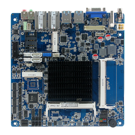
Page 16: Product Overview
EMX-BYT2-B1 User’s Manual 2.1 Product Overview • Main Memory EMX-BYT2 provides 2 x 204-pin DDR3L 1333MHz SODIMMs. • SODIMM module. Note: The Platform requires DDR3L SODIMMs to be populated starting with the SODIMM at DIMM1. 16 EMX-BYT2-B1 User’s Manual... - Page 17 –transferring data to or from the SD card-then removing the SD card, is not a concern. Customers have the option to enable a default D3 device setting to extend the life of the SD card interface, if supported by the OS. EMX-BYT2-B1 User’s Manual 17...
-
Page 18: Jumper And Connector List
Miscellaneous setting connector 1 5 x 2 header, pitch 2.54 mm FPT2 Miscellaneous setting connector 2 5 x 2 header, pitch 2.54 mm DIMM1/2 204-pin DDR3L DIMM socket FAUD1 Front Audio connector 5 x 2 header, pitch 2.54 mm 18 EMX-BYT2-B1 User’s Manual... - Page 19 4 x 1 wafer, pitch 2.54mm SPWR1/2 EC_Program 5 x 2 header, pitch 2.00 mm DC Power-in connector SIM1 SIM card slot HDMI1 HDMI connector LOUT1 Line-out audio jack MIC1 Mic-in audio jack VGA1 VGA connector EMX-BYT2-B1 User’s Manual 19...
-
Page 20: Setting Jumpers & Connectors
2.3.2 SATA2/MSATA1 mPCIe slot selector (JMSW1) SATA2 Connector * (SATA2 Connector enabled, MSATA1 slot Disabled) MSATA1 mPCIe slot (MSATA1 slot enabled, SATA2 Connector Disabled) * Default Note: SATA2/MSATA1 shared SATA signal, can not be used simultaneously. 20 EMX-BYT2-B1 User’s Manual... -
Page 21: Lvds Back Light Power Selection (Jsbkl1)
User’s Manual 2.3.3 LVDS Back Light power selection (JSBKL1) PWM Mode*(Max current: 2A) DC Mode(Max current: 2A) * Default 2.3.4 AT/ATX Power Mode Select (JSATX1) ATX* * Default EMX-BYT2-B1 User’s Manual 21... -
Page 22: Clear Cmos (Cmos1)
EMX-BYT2-B1 User’s Manual 2.3.5 Clear CMOS (CMOS1) Protect* Clear CMOS * Default 2.3.6 LCD Inverter connector (JBKL1) Signal Max current +12V LVDS_BKLTEN LVDS_BKLADJ 22 EMX-BYT2-B1 User’s Manual... -
Page 23: Serial Port 1/2 Connector (Com1/2)
User’s Manual 2.3.7 Serial port 1/2 connector (COM1/2) COM1 COM2 Signal PIN PIN Signal 2.3.8 Serial port 3/4/5/6 connector (COM3/4/5/6) COM6 COM5 COM4 COM3 Signal PIN PIN Signal EMX-BYT2-B1 User’s Manual 23... -
Page 24: Serial Port 1 Rs485/422 Mode Connector (Jrs485)
2.3.9 Serial Port 1 RS485/422 Mode connector (JRS485) RS-422 Signal PIN PIN Signal 422RX+ 422TX+ 422RX- 422TX- RS-485 Signal PIN PIN Signal 485TX+ 485TX- 2.3.10 General purpose I/O connector (DIO1) Signal PIN PIN Signal SMB_CLK SMB_DATA 24 EMX-BYT2-B1 User’s Manual... -
Page 25: Sata Power Connector 1/2 (Spwr1/2)
User’s Manual 2.3.11 SATA Power connector 1/2 (SPWR1/2) SPWR1 SPWR2 Signal Max current +V5S_SATA +V12S_SATA 2.3.12 Power connector (PWR1) Signal Signal +VIN_12V +VIN_12V EMX-BYT2-B1 User’s Manual 25... -
Page 26: Usb Connector 3 (Usb3)
EMX-BYT2-B1 User’s Manual 2.3.13 USB connector 3 (USB3) Signal Signal +V5A_USB01 +V5A_USB01 USB_DN0 USB_DN1 USB_DP0 USB_DP1 2.3.14 Battery connector (BT1) Signal 26 EMX-BYT2-B1 User’s Manual... -
Page 27: Lvds Connector (Lvds1/Edp)
2.3.15 LVDS connector (LVDS1/eDP) Signal PIN PIN Signal LVDS_VDD33V/EDP_VDD33V LVDS_VDD5V EDP_DDC_SCL EDP_DDC_DAT LVDS_DATAP1/EDP_TX1P LVDS_DATAP0/EDP_HPD LVDS_DATAN1/EDP_TX1N LVDS_DATAN0 LVDS_DATAP3 16 LVDS_DATAP2/EDP_TX0P LVDS_DATAN3 18 LVDS_DATAN2/EDP_TXN0 LVDS_DATAP5 LVDS_DATAP4 LVDS_DATAN5 LVDS_DATAN4 LVDS_DATAP7 LVDS_DATAP6 LVDS_DATAN7 LVDS_DATAN6 LVDS_CLK2P LVDS_CLK1P/EDP_AUXP LVDS_CLK2N LVDS_CLK1N/EDP_AUXN LVDS_VDD12V LVDS_VDD12V EMX-BYT2-B1 User’s Manual 27... -
Page 28: Audio Connector (Faud1)
2.3.17.1 Signal Description –Front Audio connector (FAUD1) Signal Signal Description LINE2_JD AUDIO IN (LINE_RIN/LIN)sense pin MIC2_JD MIC IN (MIC_RIN/LIN) sense pin 2.3.18 LPC connector (JLPC1) Signal PIN PIN Signal LPC_SERIRQ LPC_DEG_CLK LPC_AD3 LPC_FRAME# LPC_AD2 PLT_RST# LPC_AD1 +3.3V LPC_AD0 28 EMX-BYT2-B1 User’s Manual... -
Page 29: Ec_Program (Ec1)
User’s Manual 2.3.19 EC_Program (EC1) Signal PIN PIN Signal EC_SMDATA_DBG 10 EC_SMCLK_DBG EC_HOLD# EC_FSMOSI EC_FSMIOSO EC_FSCK EC_FSCE# +3.3A_ECSPI 2.3.20 PS/2 keyboard & mouse connector (KBMS1) Signal PIN PIN Signal KBDAT KBCK +5VSB MSDAT MSCK EMX-BYT2-B1 User’s Manual 29... -
Page 30: Bios Connector (Bios1)
EMX-BYT2-B1 User’s Manual 2.3.21 BIOS connector (BIOS1) Signal PIN PIN Signal +V1.8A_SPI SPI_ROM_CS0# SPI_ROM_CLK SPI_ROM_R_MISO SPI_ROM_MOSI SPI_ROM_HOLD# 2.3.22 Sony/Philips Digital Interface (SPDIF1) Signal SPDIF_OUT 30 EMX-BYT2-B1 User’s Manual... -
Page 31: Speaker Connector (Spk1)
User’s Manual 2.3.23 Speaker connector (SPK1) Signal RSPK- RSPK+ LSPK- LSPK+ 2.3.24 Miscellaneous setting connector 1 (FPT1) Signal PIN PIN Signal +HD_LED +PWR_LED -HD_LED -PWE_LED +Reset +PWR_BNT -Reset -PWR_BNT EMX-BYT2-B1 User’s Manual 31... -
Page 32: Miscellaneous Setting Connector 2 (Fpt2)
EMX-BYT2-B1 User’s Manual 2.3.25 Miscellaneous setting connector 2 (FPT2) Signal PIN PIN Signal Speaker+ BLK_VR(10K) BLK_UP BLK_DN Speaker- 2.3.26 LED indicator connector 1 (LED1) Signal L1_1000#_LED L1_100#_LED L1_ACT_N L1_ACT_P 32 EMX-BYT2-B1 User’s Manual... -
Page 33: Led Indicator Connector 2 (Led2)
User’s Manual 2.3.27 LED indicator connector 2 (LED2) Signal L2_1000#_LED L2_100#_LED L2_ACT_N L2_ACT_P 2.3.28 CPU fan connector (FAN1) Signal +12V CPU_FANIN CPU_FANOUT EMX-BYT2-B1 User’s Manual 33... -
Page 34: Bios Setup
EMX-BYT2-B1 User’s Manual 3.BIOS Setup 34 EMX-BYT2-B1 User’s Manual... -
Page 35: Introduction
If you do not press the keys at the correct time and the system does not boot, an error message will be displayed and you will again be asked to. Press F1 to Continue, DEL to enter SETUP EMX-BYT2-B1 User’s Manual 35... -
Page 36: Using Setup
Note: Some of the navigation keys differ from one screen to another. To Display a Sub Menu Use the arrow keys to move the cursor to the sub menu you want. Then press <Enter>. A “” pointer marks all sub menus. 36 EMX-BYT2-B1 User’s Manual... -
Page 37: Getting Help
BIOS Vendor and your systems manufacturer to provide the absolute maximum performance and reliability. Even a seemingly small change to the chipset setup has the potential for causing you to use the override. EMX-BYT2-B1 User’s Manual 37... -
Page 38: Bios Setup
<Enter> to accept and enter the sub-menu. 3.6.1 Main Menu This section allows you to record some basic hardware configurations in your computer and set the system clock. 38 EMX-BYT2-B1 User’s Manual... -
Page 39: System Language
Visit the Avalue website (www.avalue.com.tw) to download the latest product and BIOS information. 3.6.2 Advanced Menu This section allows you to configure your CPU and other system devices for basic operation through the following sub-menus. EMX-BYT2-B1 User’s Manual 39... -
Page 40: Trusted Computing
3.6.2.1 Trusted Computing Item Options Description Enables or Disables BIOS support for security Security Device Disable, device. O.S. will not show Security Device. Support Enable[Default] TCG EFI protocol and INT1A interface will not be available. 3.6.2.2 ACPI Settings 40 EMX-BYT2-B1 User’s Manual... -
Page 41: It8528 Super Io Configuration
2 min 10 min 30 min 3.6.2.3 IT8528 Super IO Configuration You can use this item to set up or change the IT8528 Super IO configuration for serial ports. Please refer to 3.6.2.3.1~ 3.6.2.3.6 for more information. EMX-BYT2-B1 User’s Manual 41... -
Page 42: Serial Port 1 Configuration
IO=3F8h; IRQ=3,4,5,6,7,9,10,11,12; Select an optimal setting for Super IO Change Settings IO=2F8h; IRQ=3,4,5,6,7,9,10,11,12; Device IO=3E8h; IRQ=3,4,5,6,7,9,10,11,12; IO=2E8h; IRQ=3,4,5,6,7,9,10,11,12; UART 232[Default], UART 232 422 485 UART 422, Change the Serial Port as RS232/ 422/ 485 UART 485 42 EMX-BYT2-B1 User’s Manual... -
Page 43: Serial Port 2 Configuration
Disabled Serial Port Enable or Disable Serial Port (COM) Enabled[Default], Auto[Default] IO=2F8h; IRQ=3; IO=3F8h; IRQ=3,4,5,6,7,9,10,11,12; Select an optimal setting for super IO Change Settings IO=2F8h; IRQ=3,4,5,6,7,9,10,11,12; Device IO=3E8h; IRQ=3,4,5,6,7,9,10,11,12; IO=2E8h; IRQ=3,4,5,6,7,9,10,11,12; 3.6.2.3.3 Serial Port 3 Configuration EMX-BYT2-B1 User’s Manual 43... -
Page 44: Serial Port 4 Configuration
3.6.2.3.4 Serial Port 4 Configuration Item Option Description Disabled Serial Port Enable or Disable Serial Port (COM) Enabled[Default], Auto[Default] IO=2E8h; IRQ=7; IO=3E8h; IRQ=3,4,5,6,7,10,11,12; Select an optimal setting for super IO Change Settings IO=2E8h; IRQ=3,4,5,6,7,10,11,12; Device IO=200h; IRQ=3,4,5,6,7,10,11,12; IO=208h; IRQ=3,4,5,6,7,10,11,12; 44 EMX-BYT2-B1 User’s Manual... -
Page 45: Serial Port 5 Configuration
Disabled Serial Port Enable or Disable Serial Port (COM) Enabled[Default], Auto[Default] IO=200h; IRQ=11; IO=3E8h; IRQ=3,4,5,6,7,10,11,12; Select an optimal setting for super IO Change Settings IO=2E8h; IRQ=3,4,5,6,7,10,11,12; Device IO=200h; IRQ=3,4,5,6,7,10,11,12; IO=208h; IRQ=3,4,5,6,7,10,11,12; 3.6.2.3.6 Serial Port 6 Configuration EMX-BYT2-B1 User’s Manual 45... -
Page 46: H/W Monitor
IO=208h; IRQ=10; IO=3E8h; IRQ=3,4,5,6,7,10,11,12; Select an optimal setting for super IO Change Settings IO=2E8h; IRQ=3,4,5,6,7,10,11,12; Device IO=200h; IRQ=3,4,5,6,7,10,11,12; IO=208h; IRQ=3,4,5,6,7,10,11,12; 3.6.2.4 H/W Monitor Item Options Description Disabled Smart Fan Function Enable or Disable Smart Fan Enabled[Default], 46 EMX-BYT2-B1 User’s Manual... -
Page 47: S5 Rtc Wake Settings
Enable or disable System wake on alarm event. Disabled[Default], Select FixedTime, system will wake on the Wake system from S5 Fixed Time hr::min::sec specified. Select DynamicTime, Dynamic Time System will wake on the current time + Increase minute(s). 3.6.2.6 Serial Port Console Redirection EMX-BYT2-B1 User’s Manual 47... -
Page 48: Cpu Configuration
Windows XP SP2, SuSE Linux 9.2, RedHat Enterprise 3 Update 3.) When enabled, a VMM can utilize the Intel Virtualization Disabled, additional hardware capabilities provided by Technology Enabled[Default] Virtualization Technology Disabled[Default], Power Technology Energy Efficient Enable the power management features. Custom 48 EMX-BYT2-B1 User’s Manual... -
Page 49: Socket 0 Cpu Information
User’s Manual 3.6.2.7.1 Socket 0 CPU Information 3.6.2.8 PPM Configuration Item Options Description Disabled[Default], CPU C state Report Enable/Disable CPU C state report to OS Enabled EMX-BYT2-B1 User’s Manual 49... -
Page 50: Ide Configuration
SATA Speed Support Gen1 or Gen2 Gen2[Default] Port0 ODD SATA ODD Port Port1 ODD SATA ODD is Port0 or Port1 No ODD[Default] IDE Mode SATA Mode Select IDE/AHCI AHCI Mode[Default] Enabled[Default] Serial-ATA Port 0/1 Enable/Disable Serial ATA Port0/1 Disabled, 50 EMX-BYT2-B1 User’s Manual... -
Page 51: Lpss & Scc Configuration
Enabled[Default] SCC SDIO Support SCC SDIO Support Enable/Disable Disabled, Enabled[Default] SCC SD Card Support SCC SD Card Support Enable/Disable Disabled, SDR25 Support for Enabled[Default] Disable/Enable SDR25 Capability in SD Card SDCard Disabled, controller EMX-BYT2-B1 User’s Manual 51... -
Page 52: Network Stack Configuration
EMX-BYT2-B1 User’s Manual 3.6.2.11 Network Stack Configuration Item Options Description Disabled[Default] Network Stack Enable/Disable UEFI Network Stack Enabled 3.6.2.12 CSM Configuration Item Options Description Disabled, CSM Support Enable/Disable CSM Support Enabled[Default] 52 EMX-BYT2-B1 User’s Manual... -
Page 53: Sdio Configuration
Auto[Default] Auto Option: Access SD device in DMA mode if ADMA controller supports it,otherwise in PIO mode. DMA SDIO Access Mode SDMA Option: Access SD device in DMA mode.PIO Option: Access SD device in PIO mode. EMX-BYT2-B1 User’s Manual 53... -
Page 54: Usb Configuration
Maximum time the device will take before it Auto[Default] properly reports itself to the Host Controller. Device power-up delay ‘Auto’ uses default value: for a Root port it is Manual 100ms, for a Hub port the delay is taken form 54 EMX-BYT2-B1 User’s Manual... -
Page 55: Security Configuration
Enable/Disable BIOS AT Code from Running Disabled[Default], Enabled Inter® AT Platform Enable/Disable BIOS AT Code from Running Disabled[Default], TXE OVERWRITE. NORMAL: OverWrite Pin as OVERWRITE TXE OVERWRITE high. (TXE enabled) OVERWRITE:OverWrite NORMAL[Default] Pin as low. (TXE disabled) EMX-BYT2-B1 User’s Manual 55... -
Page 56: Driver Health
EMX-BYT2-B1 User’s Manual 3.6.2.16 Driver Health 3.6.2.16.1 Inter® PRO/1000 6.6.04 PCI-E Healthy 56 EMX-BYT2-B1 User’s Manual... -
Page 57: Chipset
User’s Manual 3.6.3 Chipset 3.6.3.1 North Bridge Item Option Description Dynamic 2 GB 2.25 GB Max TOLUD Maximum Value of TOLUD. 2.5 GB 2.75 GB 3 GB[Default] EMX-BYT2-B1 User’s Manual 57... -
Page 58: Intel Igd Configuration
Graphics Memory size used by the Internal 384M/416M/448M/ Graphics Device. 480M/512M 128MB Select DVMT 5.0 Total Graphics Memory size DVMT Total Gfx Mem 256MB[Default] used by the Internal Graphics Device. 128MB Aperture Size Select the Aperture Size 256MB[Default] 58 EMX-BYT2-B1 User’s Manual... -
Page 59: Igd - Lcd Control
1440x900 18/2 1600x1200 24/2 1366x768 24/1 1920x1080 24/2 1680x1050 24/2 or 7513-eDP BIOS[Default] Brightness Control LVDS Brightness Control Method. 1.BIOS BR Button Method 2.Brightness Button 3.Variable Resistor LVDS Back Light Select LVDS back light PWM duty. 100%[Default] EMX-BYT2-B1 User’s Manual 59... -
Page 60: South Bridge
High Precision Timer Enable or Disable the High Precision Event Timer. Disabled 11db 14db AUD Gain Setting Select db Value of the AUD Gain 19db[Default] 25db PCIE x1 PCIEX1 Setting Select PCIE x1/ MPCIE of the PCIEx1_SET MPCIE[Default] 60 EMX-BYT2-B1 User’s Manual... -
Page 61: Azalia Hd Audio
Enabled = Azalia will be Audio Controller Enabled[Default], unconditionally Enabled. Auto = Azalia will be enabled if present disabled otherwise. Disabled HDMI Port B Enable/Disable HDMI Port B Enabled[Default], 3.6.3.2.2 USB Configuration EMX-BYT2-B1 User’s Manual 61... -
Page 62: Pci Express Configuration
Windows 7 3.6.3.2.3 PCI Express Configuration Item Option Description PCI Express Port 1(i210/i211) Enabled[Default], Enable or Disable the PCI Express Port 0/1/2/3 Disabled 0/1/2/3 in the Chipset. Auto[Default] Speed Gen 2 Configure PCIe Port Speed Gen 1 62 EMX-BYT2-B1 User’s Manual... -
Page 63: Security
User’s Manual 3.6.4 Security Administrator Password Set setup Administrator Password User Password Set User Password 3.6.4.1 Secure Boot menu EMX-BYT2-B1 User’s Manual 63... -
Page 64: Key Management
Image Execution policy Custom[Default] and manage Secure Boot Keys. 3.6.4.1.1 Key Management Item Option Description Disabled[Default] Install Factory default Secure Boot Keys when Default Key Provision Enabled, System is in Setup Mode. 64 EMX-BYT2-B1 User’s Manual... -
Page 65: Boot
Enables or disables boot with initialization of a Disabled[Default] Fast Boot minimal set of devices required to launch active Enabled boot option. Has no effect for BBS boot options. Boot Option #1/2 Set the system boot order. EMX-BYT2-B1 User’s Manual 65... -
Page 66: Save And Exit
The setup program then exits and reboots the controller. This option restores all BIOS settings to the factory default. This option is Restore Defaults useful if the controller exhibits unpredictable behavior due to an incorrect or inappropriate BIOS setting. 66 EMX-BYT2-B1 User’s Manual... - Page 67 User’s Manual Launch EFI Shell from Attempts to Launch EFI Shell application (Shellx64.efi) from one of the filesystem device available filesystem devices. EMX-BYT2-B1 User’s Manual 67...
-
Page 68: Drivers Installation
EMX-BYT2-B1 User’s Manual 4. Drivers Installation Note: Installation procedures and screen shots in this section are for your reference and may not be exactly the same as shown on your screen. 68 EMX-BYT2-B1 User’s Manual... -
Page 69: Install Chipset Driver
Note: The installation procedures and screen shots in this section are based on Windows 10 operation system. Step 3. Click Install. Step1. Click Next. Step 4. Click Finish to complete setup. Step 2. Click Accept. EMX-BYT2-B1 User’s Manual 69... -
Page 70: Install Txe Driver
Windows 10 operation system. Step 3. Click Next to continue installation. Step 4. Click Finish to complete setup. Step1. Click Next to start installation. Step 2. Click Next. 70 EMX-BYT2-B1 User’s Manual... -
Page 71: Install Vga Driver
Windows 10 operation system. Step 3. Click Next. Step 1. Click Next to continue installation. Step 4. Click Next. Step 2. Step 5. Click Finish to complete setup. Click Yes to accept license agreement. EMX-BYT2-B1 User’s Manual 71... -
Page 72: Install Audio Driver
All drivers can be found on the Avalue Official Website: http://www.avalue.com.tw. Note: The installation procedures and screen shots in this section are based on Windows 10 operation system. Step 1. Click Next to continue setup. Step 2. Click Finish to complete the setup. 72 EMX-BYT2-B1 User’s Manual... -
Page 73: Install Ethernet Driver
Windows 10 operation system. Step 3. Click Next. Step 4. Click Install to proceed. Step 1. Click Next. Step 2. Click Next to accept license Step 5. Click Finish to complete the setup agreement. EMX-BYT2-B1 User’s Manual 73... -
Page 74: Install Usb 3.0 Driver
Windows 10 operation system. Step 3. Click Next to continue installation. Step 4. Wait while installing. Step1. Click Next to start installation. Step 2. Click Yes. Step 5. Click Finish to complete setup. 74 EMX-BYT2-B1 User’s Manual... -
Page 75: Install Mbi Driver
Windows 10 operation system. Step 3. Click Next to continue installation. Step 4. Click Finish to complete setup. Step1. Click Next to start installation. Step 2. Click Yes. EMX-BYT2-B1 User’s Manual 75... -
Page 76: Mechanical Drawing
EMX-BYT2-B1 User’s Manual 5. Mechanical Drawing 76 EMX-BYT2-B1 User’s Manual... - Page 77 User’s Manual Unit: mm EMX-BYT2-B1 User’s Manual 77...
Need help?
Do you have a question about the EMX-BYT2-B1 and is the answer not in the manual?
Questions and answers