
Related Manuals for Moons' STF-Multi axis Series


Summary of Contents for Moons' STF-Multi axis Series
- Page 1 STF-Multi axis Series Step-Servo System Hardware Manual STF-2XU-ECX/STF-2XU-ECX-S STF-4X-ECX/STF-4X-ECX-S STF-4XU-ECX/STF-4XU-ECX-S SHANGHAI AMP&MOONS’ AUTOMATION CO.,LTD Version 1.0 11/14/2023...
-
Page 2: Table Of Contents
STF-Multi axis Series Hardware Manual 1 Introduction ........................3 1.1 Features ........................3 1.2 Safety Instructions ....................7 2 Getting Started .........................8 2.1 Choose a Power Suppl..................8 2.1.1 Voltage ....................8 2.1.2 How to use the Connector ..............9 2.2 Connect the Power ....................10 2.3 Installing Software ....................12 2.4 Connecting the EtherCAT ..................15... -
Page 3: Introduction
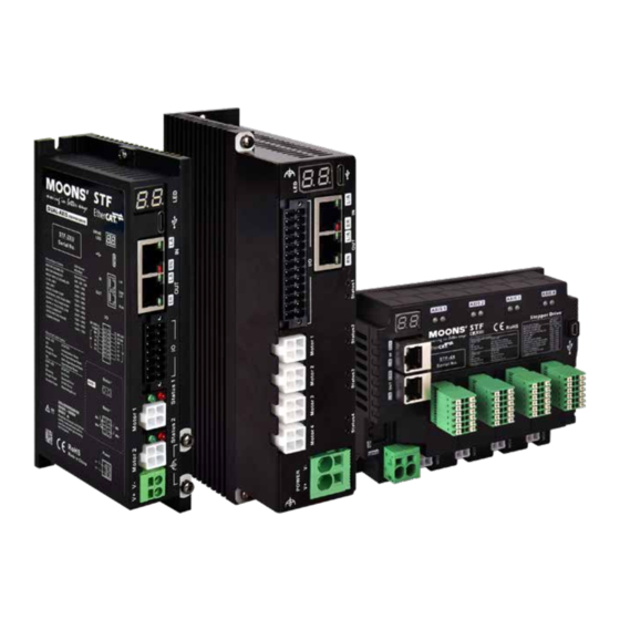
STF-Multi axis Series Hardware Manual 1 Introduction Thank you for choosing MOONS’ STF Multi-axis Step-Servo motor driver. The STF Multi-axis series is a high-performance bus-controlled 2 - or 4-axis Step-Servo motor driver that integrates the functionality of an intelligent motion controller to run as a standard EtherCAT slave station with support for CANopen over EtherCAT (CoE). - Page 4 STF-Multi axis Series Hardware Manual • Output current: STF05-2XU Continuous output current 2x5A STF10-2XU Continuous output current 2x10A STF05-4X/4XU Continuous output current 4x5A STF10-4X/4XU Continuous output current 4x10A • STF05/10-2XU/4XU: 3 optically isolated input,5~24V 1 optically isolation digital output: maximum withstand voltage 30V, maximum output current...
- Page 5 STF-Multi axis Series Hardware Manual Power Output Configuration Type Input Output Communication Supply Current Port 2x2 optical isolated digital 2x5A max 2x3 optical output: STF05-2XU-ECX EtherCAT USB Type-C isolation input (peak of sin) 2x1 Brake direct drive,control signal output 2x2 optical isolated digital...
- Page 6 STF-Multi axis Series Hardware Manual STF05/10-4X-ECX;STF05/10-4X-ECX-S STF05/10-4XU-ECX;STF05/10-4XU-ECX-S STF05/10-2XU-ECX;STF05/10-2XU-ECX-S Version 1.0 400-820-9661 11/14/2023...
-
Page 7: Safety Instructions
STF-Multi axis Series Hardware Manual 1.2 Safety Instructions Only qualified personnel should transport, assemble, install, operate, or maintain this equipment. Properly qualified personnel are persons who are familiar with the transport, assembly, installation, operation, and maintenance of motors, and who meet the appropriate qualifications for their jobs. -
Page 8: Getting Started
STF-Multi axis Series Hardware Manual 2 Getting Started You need to make the following preparations: • A power supply suitable for the drive, please read the section titled “Choosing the Right power Supply” below to help you choose the right power supply. -
Page 9: How To Use The Connector
STF-Multi axis Series Hardware Manual 2.1.2 How to use the Connector STF stepper motor drivers are used in combination with different Stepper-servo, and the recommended power supply current capacity at different supply voltages is shown in the table below. Under normal circumstances, the input current of the driver power supply is smaller than... -
Page 10: Connect The Power
STF-Multi axis Series Hardware Manual 2.2 Connect the Power The STF multi-axis series comes with a power connector. The first part on the left side of the connector is the V+ of the power supply, and the second part is the V- of the power supply. - Page 11 STF-Multi axis Series Hardware Manual 2.2.1 How to use the Connector 1.The following diagram shows the internal structure of the connector. 2.Insert the terminal block into the connector 3.Metal shrapnel inside the connector can jam the terminals 4.When it is necessary to remove the wire harness, press the orange plastic part to pull out the wire harness terminal Version 1.0...
-
Page 12: Installing Software
STF-Multi axis Series Hardware Manual 2.3 Installing Software Stepper Suite is a PC-based stepper server application configuration and debugging software that can be used to configure and set various operating modes, adjust servo tuning parameters, and test and evaluate drive performance. The software has powerful functions, user-friendly interface and easy operation. - Page 13 STF-Multi axis Series Hardware Manual EtherCAT Input Communication Interface EtherCAT Output I/O Connector Ground Screws Power Connector Motor Connector STF-4X-ECX Communication Interface EtherCAT Input EtherCAT Output I/O Connector Motor Connector Power Connector Ground Screws STF-4XU-ECX Version 1.0 400-820-9661 11/14/2023...
- Page 14 STF-Multi axis Series Hardware Manual EtherCAT Input EtherCAT Output I/O Connector Motor Connector Power Connector Ground Screws STF-2XU-ECX Version 1.0 400-820-9661 11/14/2023...
-
Page 15: Connecting The Ethercat
STF-Multi axis Series Hardware Manual 2.4 Connecting the EtherCAT Dual RJ-45 connectors accept standard Ethernet cables and are categorized as 100BASE-TX (100 Mb/sec) ports. CAT5 or CAT5e (or higher) cables should be used. The IN port connects to a master, or to the OUT port of an upstream node. -
Page 16: Led Panel Display
STF-Multi axis Series Hardware Manual 2.6 LED panel display The STF multi-axis series drives have two 7-segment digital tubes, LED1 and LED2, for displaying the EtherCAT address. When the drive is operating normally, the 7-segment digital tube displays the drive EtherCAT address (Physical Address or EtherCAT ID). -
Page 17: Inputs And Outputs
STF-Multi axis Series Hardware Manual 3 Inputs and Outputs Inputs and outputs of STF-2XU/4XU drivers include: • 3 optically isolated digital signal input, 5~24V • 1 optically isolation of digital signal output: maximum withstand voltage 30V, maximum current 100mA •... - Page 18 STF-Multi axis Series Hardware Manual YCOM 24V+ BRAKE XCOM 24V- I/O Connector Diagram STF05/10-4X-ECX STF05/10-4X-ECX-S Driver I/O Interface Pin Definitions Signal Definition Signal Definition YCOM 24V+_BR XCOM 24V-_BR Version 1.0 400-820-9661 11/14/2023...
-
Page 19: Digital Inputs
STF-Multi axis Series Hardware Manual Digital Inputs The STF multi-axis series drives contain either 3 (-2XU Series/-4XU Series) or 5 (-4X Series) digital isolated inputs. The function of each input signal can be configured by the software Stepper Suite. The input signal corresponds to the function as follows:... -
Page 20: Digital Outputs
STF-Multi axis Series Hardware Manual 3.2 Digital Outputs The STF multi-axis series drives contain either 1 (-2XU Series/4XU Series) or 2 (-4X Series) digital isolated outputs. The function of each output signal can be configured by the software Stepper Suite, and the output signal corresponds to the function as follows:... -
Page 21: Y2 Brake Out
STF-Multi axis Series Hardware Manual 3.3 Y2 Brake Out STF multi-axis series driver includes 1 brake direct drive output, photoelectric isolation. The brake output signal function can be configured by the software Stepper Suite. Y2 brake signal output wiring: Warning: Do not connect the output to more than 24V DC voltage, the current flowing into the output do not exceed 1A. -
Page 22: Sto Function Precautions
STF-Multi axis Series Hardware Manual 3.4.3 STO function precautions 1) If you do not need to use the STO function, please ensure that the STO docking terminal equipped with the factory is correctly inserted in the port 2) To use the STO function, please make sure to understand the working mechanism and safety... -
Page 23: Logical Relationship Between Sto Function And Input Signal
STF-Multi axis Series Hardware Manual 3.4.5 Logical relationship between STO function and input signal SF1 input state SF2 input state STO functional state no-trigger trigger trigger trigger Note: Conduction ON input voltage requires 24VDC, (each input signal has a minimum current capacity of 5mA) OFF The input voltage must be 0 to 5VDC or left blank. -
Page 24: Reference Materials
STF-Multi axis Series Hardware Manual 6 Reference Materials 6.1 Technical Specifications Power Amplifier Amplifier Type Dual H-Bridge, 4 Quadrant Current Control 16KHz 4 Quadrant SRF05-2XU-ECX:Continuous Current 2x5A max STF10-2XU-ECX:Continuous Current 2x10Amax SRF05-2XU-ECX-S:Continuous Current 2x5A max STF10-2XU-ECX-S:Continuous Current 2x10Amax STF05-4X-ECX:Continuous 4x5Amax STF10-4X-ECX:Continuous 4x10A max... - Page 25 STF-Multi axis Series Hardware Manual STF-2XU: 2x2-way opto-isolated output Y1: Opto-isolated, open collector, 30V, 100mA Y2: Brake direct drive, opto-isolated, 24V, 1A. STF-4X: 4x3-way opto-isolated output Digital Outputs Y1,Y3: Opto-isolated, Open Collector, 30V, 100mA Y2: Brake Direct Drive, Optoisolated, 24V, 1A.
-
Page 26: Drive Dimensions
STF-Multi axis Series Hardware Manual 6.2 Drive Dimensions 2- 4.2安装孔 2-M3接地 STF-4XU Units: mm 2- 4.4 STF-4X Units: mm Version 1.0 400-820-9661 11/14/2023... - Page 27 STF-Multi axis Series Hardware Manual STF-2XU Units: mm Version 1.0 400-820-9661 11/14/2023...
-
Page 28: Recommended Motor
STF-Multi axis Series Hardware Manual 6.3 Recommended Motor ■ Standard type step motor Holding Drive Current Rotor Mass Length Mass Lead Torque Setting Range※ Inertia Model Features Dielectric number g.cm Strength AM8HY2050-01N Single Shaft 29.5 0.02 0.04 AM8HY2050-02N Double Shaft 0.1~0.5... - Page 29 STF-Multi axis Series Hardware Manual ■ IP65 type motor Drive Current Rotor 静力矩 Length Mass Mass (N.m) Setting Range※ Inertia Lead Model Features Dielectric number Strength g.cm² AM23HS2450-03 IP65 61.7 1.25 0.1~4.5 AM23HS3455-05 IP65 83.7 0.1~4.5 500VAC/ AM24HS5401-44N IP65 94.5 0.1~4.5...
- Page 30 STF-Multi axis Series Hardware Manual ■ With brake type motor Holding Drive Current Rotor Length Mass Mass Torque Setting Range※ Inertia Lead Model Features Dielectric number Strength g.cm AM17HD4452-BR01 Brake Motor 60.3 0.285 0.1~1.8 0.38 AM17HD2438-BR01 Brake Motor 65.8 0.46 0.1~1.8...
-
Page 31: Torque Curves
STF-Multi axis Series Hardware Manual 6.4 Torque Curves AM11HS1008 AM8HY4043 AM8HY2050 Microstep: 20000 steps/rev Microstep: 20000 steps/rev Microstep: 20000 steps/rev Current: 1.6A(Peak) Current: 0.5A(Peak) Current: 0.5A(Peak) 0.040 0.016 0.035 0.014 0.08 0.030 0.012 0.025 0.06 0.01 0.020 0.008 0.04 0.015 0.006... - Page 32 STF-Multi axis Series Hardware Manual AM23HS84B0 AM23HSA4B0 Microstep: 20000 steps/rev Microstep: 20000 steps/rev Microstep: 20000 steps/rev Current: 4.5A(Peak) Current: 4.5A(Peak) Current: 4.5A(Peak) Speed(rps) Speed(rps) Speed(rps) AM24HS5401 AM24HS2402 AM34HD0404 Microstep: 20000 steps/rev Microstep: 20000 steps/rev Microstep: 20000 steps/rev Current: 4.5A(Peak) Current: 4.5A(Peak) Current: 7.0A(Peak)
-
Page 33: Accessories
STF-Multi axis Series Hardware Manual 7 Accessories 7.1 Standard Accessories(Included) amount Catagory Description Model 39-01-3048 Molex Motor Connector Plastic Housing (J2) 39-00-0038 Molex Motor Connector pin 15EDGKNHG-3.5-14P-13-00A(H) IO Connector Plug SSDC-2XU 15EDGKNHG-3.5-14P-13-00A(H) 15EDGKNH-3.5-12P-14-00A(H) IO Connector Plug SSDC-4X 15EDGKNH-3.5-12P-14-00A(H) 15EDGKNHG-3.5-26P-13-00A(H) IO Connector Plug SSDC-4XU 15EDGKNHG-3.5-26P-13-00A(H) -
Page 34: Contacting Moons
STF-Multi axis Series Hardware Manual 8 Contacting MOONS’ Customer Service Center +86-400-820-9661 MOONS’ Headquarter North America Company MOONS' Industries (AMERICA), Inc. (Chicago) 168 Mingjia Road, Minhang District, Shanghai 201107, P.R. China 1113 North Prospect Avenue, Itasca, IL 60143,USA MOONS’ Taicang MOONS’...
Need help?
Do you have a question about the STF-Multi axis Series and is the answer not in the manual?
Questions and answers