
Related Manuals for Moons' SSDC Multi-axis Series


Summary of Contents for Moons' SSDC Multi-axis Series
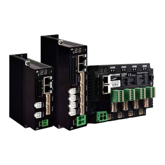
- Page 1 SSDC Multi-axis Series Step-Servo System Hardware Manual SSDC-2XU-ECX/SSDC-2XU-ECX-S SSDC-4X-ECX/SSDC-4X-ECX-S SSDC-4XU-ECX/SSDC-4XU-ECX-S SHANGHAI AMP&MOONS’ AUTOMATION CO.,LTD. Rev. 1.0 08/31/2023...
-
Page 2: Table Of Contents
Multi-axis Series Hardware Manual 1 Introduction ......................4 1.1 Features ....................4 1.2 Safety Instruction..................8 2 Getting Started ....................9 2.1 Choose a Power Supply ................9 2.1.1 Voltage ..................9 2.1.2 Current ..................10 2.2 Connect the Power .................. 12 2.2.1 How to use the Connector ............ - Page 3 Multi-axis Series Hardware Manual 7.2.1 Extended motor cable (For AM08RS motor) ................ 42 7.2.2 Extended motor cable (For SSDC drive and AM11RS motor) ..........43 7.2.3 Extended motor cable (For SSDC drive and AM17/23/24SS-N、AM17/23/24RS motor) ..43 7.2.4 Extended motor cable (For SSDC drive and AM34SS-N、AM34RS motor) ......43 7.2.5 Extended encoder cable (For AM08RS motor) ................44...
-
Page 4: Introduction
2 or 4 axes Step-Servo motor driver, while integrating the function of intelligent motion controller, can be paired with MOONS’RS, SS series Step-Servo motor. SSDC Multi-axis series drives can run as standard EtherCAT slaves and support CoE (CANopen over EtherCAT). - Page 5 Multi-axis Series Hardware Manual • SSDC06/10-2XU/4XU: 3 optically isolated digital input,5~24V 1 optically isolation digital output: maximum withstand voltage 30V, maximum output current 100mA 1 brake direct drive control signal output: maximum withstand voltage 24V, maximum current 1A SSDC06/10-4X: 5 optically isolated digital signal input,5~24V 2 optically isolation of digital signal output: maximum withstand voltage 30V, maximum output current 100mA 1 brake direct drive control signal output: maximum withstand voltage 24V, maximum current 1A...
- Page 6 Multi-axis Series Hardware Manual Power Output Configuration Output Communication Type Input Port Supply Current 2X1 optical isolated digital 2x6A max output: 2x3 optical SSDC06-2XU-ECX EtherCAT USB Type-C isolated input (peak of sin) 2X1 brake direct drive control signal output 2X1 optical isolated digital 2x10A max output: 2x3 optical...
- Page 7 Multi-axis Series Hardware Manual SSDC06/10-4X-ECX;SSDC06/10-4X-ECX-S SSDC06/10-4XU-ECX;SSDC06/10-4XU-ECX-S SSDC06/10-2XU-ECX;SSDC06/10-2XU-ECX-S Rev. 1.0 400-820-9661 09/27/2023...
-
Page 8: Safety Instruction
Multi-axis Series Hardware Manual 1.2 Safety Instruction Only qualified personnel should transport, assemble, install, operate, or maintain this equipment. Properly qualified personnel are persons who are familiar with the transport, assembly, installation, operation, and maintenance of motors, and who meet the appropriate qualifications for their jobs. To minimize the risk of potential safety problems, all applicable local and national codes regulating the installation and operation of equipment should be followed. -
Page 9: Getting Started
Multi-axis Series Hardware Manual 2 Getting Started • You need to make the following preparations: • A power supply suitable for the drive, please read the section titled “Choose a Power Supply” below to help you choose the right power supply. •... -
Page 10: Current
Multi-axis Series Hardware Manual 2.1.2 Current The power input currents required for SSDC Stepper-servo drivers and motors operating at different supply voltages are indicated on the curves below. Under normal circumstances, the input current of the driver power supply is smaller than the current of the drive motor, because the driver itself realizes the energy conversion function, that is, the driver amplifies a high-voltage and small-current signal into a low-voltage and high-current signal through the power switch. - Page 11 Multi-axis Series Hardware Manual AM17SS/RS Series ■ AM17SS1DG□-N AM17SS2DG□-N AM17SS3DG□-N Rated Torque Rated Torque Rated Torque Peak Torque Peak Torque Peak Torque AM17RS1DM□ AM17RS2DM□ AM17RS3DM□ Power Supply Current Power Supply Current Power Supply Current 0.35 0.25 0.15 0.05 Speed(rps) Speed(rps) Speed(rps) AM17SS4DG□-N Rated Torque...
-
Page 12: Connect The Power
2.2 Connect the Power SSDC multi-axis series products share a power connector, the first on the left side of the connector is the V+ of the power supply, the second is the V- of the power supply, be careful not to connect the reverse. -
Page 13: How To Use The Connector
Multi-axis Series Hardware Manual 2.2.1 How to use the Connector 1.The following diagram shows the internal structure of the connector. 2.Insert the terminal block into the connector 3.Metal shrapnel inside the connector can jam the terminals 4.When it is necessary to remove the wire harness, press the orange plastic part to pull out the wire harness terminal Rev. -
Page 14: Installing Software
Multi-axis Series Hardware Manual 2.3 Installing Software Stepper Suite is a PC-based Step-Servo application configuration and debugging software that can be used to configure and set various operating modes, adjust servo tuning parameters, and test and evaluate drive performance. The software has powerful functions, user-friendly interface and easy operation. - Page 15 Multi-axis Series Hardware Manual Type C Communication Interface Ground Screws EtherCAT Input I/O Connector EtherCAT Output Encoder Connector Motor Connector Power Connector EtherCAT Input Communication Interface EtherCAT Output I/O Connector Encoder Connector STO (-S Version only) Ground Screws Power Connector Motor Connector Rev.
-
Page 16: Connecting The Ethercat
Multi-axis Series Hardware Manual 2.4 Connecting the EtherCAT Dual RJ-45 connectors accept standard Ethernet cables and are categorized as 100BASE-TX (100 Mb/sec) ports. CAT5 or CAT5e (or higher) cables should be used. The IN port connects to a master, or to the OUT port of an upstream node. The OUT port connects to a downstream node. If the drive is the last node on a network, only the IN port is used. -
Page 17: Setting The Ethercat Node Id
Multi-axis Series Hardware Manual 2.5 Setting the EtherCAT Node ID When the drive’s ID is configured to be assigned by master controller in Stepper Suite software, the master controller can set the EtherCAT node Alias ID to address 0004h of SII (Slave Information Interface) EEPROM. - Page 18 Multi-axis Series Hardware Manual Encoder connector on the driver Pin No. Signal Definition Pin No. Signal Definition Encoder signalsA- Encoder signalsA+ Encoder signalsB- Encoder signalsB+ Encoder signalsZ- Encoder signalsZ+ Encoder Power Supply GND Encoder Power Supply5V Shield Ground Encoder signals Encoder signalsU+ Encoder signalsV- Encoder signalsV+...
-
Page 19: Inputs And Outputs
Multi-axis Series Hardware Manual 3 Inputs and Outputs Inputs and outputs of SSDC-2XU/4XU drivers include: • 3 optically isolated digital signal input, 5~24V • 1 optically isolation of digital signal output: maximum withstand voltage 30V, maximum current 100mA • 1 brake direct drive control signal output: maximum withstand voltage 24V, maximum current I/O Connector Diagram I/O Connector Diagram SSDC06/10-2XU-ECX... - Page 20 L/A OUT Multi-axis Series Hardware Manual SSDC06/10-4X-ECX SSDC06/10-2XU-ECX SSDC06/10-4XU-ECX YCOM 24V+ BRAKE XCOM 24V- I/O Connector Diagram SSDC06/10-4X-ECX SSDC06/10-4X-ECX-S Rev. 1.0 400-820-9661 09/27/2023...
-
Page 21: Digital Inputs
Multi-axis Series Hardware Manual 3.1 Digital Inputs The SSDC multi-axis series drives contain either 3 (-2XU/4XU) or 5 (-4X) digital isolated inputs. The function of each input signal can be configured by the software Stepper Suite. The input signal corresponds to the function as follows:... -
Page 22: Digital Outputs
Multi-axis Series Hardware Manual 3.2 Digital Outputs The SSDC multi-axis series drives contain either 1 (-2XU/4XU) or 2 (-4X) digital isolated outputs. The function of each output signal can be configured by the software Stepper Suite, and the output signal... -
Page 23: Y2 Brake Out
There are five levels: a, b, c, d, e, and PLe is the highest. The STO function of SSDC multi-axis series products can reach SIL3 level and PLe level Rev. 1.0... -
Page 24: Sto Function Precautions
Multi-axis Series Hardware Manual 3.4.3 STO function precautions 1) If you do not need to use the STO function, please ensure that the STO docking terminal equipped with the factory is correctly inserted in the port 2) To use the STO function, please make sure to understand the working mechanism and safety precautions of STO 3) After triggering the STO function, due to the presence of external forces (such as vertical axis load), the motor will rotate due to external forces. -
Page 25: Logical Relationship Between Sto Function And Input Signal
4 Mounting the Drive The SSDC multi-axis series drives can be mounted through the narrow sides of the heat sink using M3 or M4 screws. If possible, it is best to secure the drive to a smooth, flat metal surface, which helps to dissipate heat from the drive. -
Page 26: Reference Materials
Multi-axis Series Hardware Manual 6 Reference Materials 6.1 Technical Specifications Power Amplifier Amplifier Type Dual H-Bridge Current Control SSDC06-2XU-ECX:Continuous Current 2x6A max,Boost Current 2x7.5A max (1.5s);current limitation auto set-up by attached motor SSDC10-2XU-ECX:Continuous Current 2x10A max,Boost Current 2x15A max (1.5s);current limitation auto set-up by attached motor SSDC06-2XU-ECX-S:Continuous Current 2x6A max,Boost Current 2x7.5A max (1.5s);current limitation auto set-up by attached motor... - Page 27 Multi-axis Series Hardware Manual Speed Range Up to 3000rpm Filters Digital input noise filter, Analog input noise filter, Smoothing filter, PID filter, Notch filte Non-Volatile Configuration parameters are stored in the external EEPROM of the DSP Storage Protocol CoE conform CiA402, VoE(Supports update the firmware over EtherCAT) Modes of Profile Position, Profile Velocity, Profile Torque, Cyclic Synchronous Position, Cyclic Synchronous Velocity and Homing mode...
-
Page 28: Drive Dimensions
Multi-axis Series Hardware Manual 6.2 Drive Dimensions R2.1 SSDC-4XU Units: mm SSDC-4X Units: mm Rev. 1.0 400-820-9661 09/27/2023... - Page 29 Multi-axis Series Hardware Manual SSDC-2XU Units: mm Rev. 1.0 400-820-9661 09/27/2023...
-
Page 30: Recommended Motors
Multi-axis Series Hardware Manual 6.3 Recommended Motors Rotor Encoder Maximum Frame Permissible Permissible Overhung Load(N) Drive Torque Mass Model Inertia Resolution Speed Size Thrust Distance(L) from Shaft End(mm) Load counts/rev AM08RS1DMA 0.03 AM08RS2DMA 0.042 AM08RS3DMA 0.05 AM11RS1DMA 0.065 AM11RS2DMA 0.08 4096 AM11RS3DMA 0.125... -
Page 31: Motor Dimensions (Unit:mm)
Multi-axis Series Hardware Manual 6.4 Motor Dimensions (Unit:mm) AM08 Series 20.3 Max 16±0.2 29.5 Max 1.5±0.2 4-M2 3 Min Model 15±0.5 AM08RS1DMA 45.5 AM08RS2DMA 55.5 AM08RS3DMA 72.5 AM11 Series 4-M2.5 Depth 2.5 Min Model AM11RS1DMA 43.8 AM11RS2DMA 52.9 AM11RS3DMA 64.1 Rev. - Page 32 Multi-axis Series Hardware Manual AM17 Series 42.3 4-M3 Depth 4.5Min φ22 Model Connector On Cable AM17RS1DMA 59.5 φ6 Motor cable AM17RS1DMB 59.5 φ5 Housing: 39-01-3048 (Molex), 1pcs AM17RS2DMA φ6 Crimp: 39-00-0038 (Molex), 4pcs AM17RS2DMB φ5 AM17RS3DMA 73.5 φ6 Encoder cable AM17RS3DMB 73.5 φ5...
- Page 33 Multi-axis Series Hardware Manual AM23 Series 56.3 4-φ5.1 47.14 φ38.1 Model Connector On Cable Motor cable AM23RS2DMA 77.5 φ8 Housing: 39-01-3048 (Molex),1pcs AM23RS2DMB 5.85 77.5 φ6.35 Crimp: 39-00-0038 (Molex),4pcs AM23RS3DMA 99.5 φ8 Encoder cable AM23RS3DMB 5.85 99.5 φ6.35 Housing: 1-1827864-6 (Tyco),1pcs AM23RS4DMA 102.5 φ8...
- Page 34 Multi-axis Series Hardware Manual AM24 Series 47.14 4-φ4.5 φ38.1 Model Connector On Cable Motor cable Housing: 39-01-3048 (Molex),1pcs AM24RS3DMA φ10 Crimp: 39-00-0038 (Molex),4pcs Encoder cable AM24RS3DMB 20.6 φ8 Housing: 1-1827864-6 (Tyco),1pcs Crimp: 1827569-2 (Tyco),11pcs Motor cable Housing: 39-01-3048 (Molex),1pcs AM24SS3DGA-N φ10 Crimp: 39-00-0038 (Molex),4pcs Encoder cable...
- Page 35 Multi-axis Series Hardware Manual AM34 Series 69.6 4-Φ6.5 Φ73.025 Model Connector On Cable Motor cable AM34RS1DMA Housing: 39-01-3048 (Molex),1pcs Crimp: 39-00-0038 (Molex),4pcs AM34RS3DMA 117.5 Encoder cable Housing: 1-1827864-6 (Tyco),1pcs AM34RS5DMA Crimp: 1827569-2 (Tyco),15pcs Motor cable AM34SS1DGA-N Housing: 39-01-3048 (Molex),1pcs Crimp: 39-00-0038 (Molex),4pcs AM34SS3DGA-N 117.5 Encoder cable...
- Page 36 Multi-axis Series Hardware Manual AM17SS-N-BR01 Series(With brake) 42.3 4-M3 Depth 4.5Min Ø22 73.5 Model Connector On Cable AM17SS1DGA-N-BR01 59.5 φ6 Motor cable AM17SS1DGB-N-BR01 59.5 φ5 Housing: 39-01-3048 (Molex),1pcs AM17SS2DGA-N-BR01 φ6 Crimp: 39-00-0038 (Molex),4pcs AM17SS2DGB-N-BR01 φ5 AM17SS3DGA-N-BR01 73.5 φ6 Encoder cable AM17SS3DGB-N-BR01 73.5 φ5...
- Page 37 Multi-axis Series Hardware Manual AM23SS-N-BR01 Series(With brake) 56.3 47.14 4-Ø5.1 Ø38.1 Model Connector On Cable AM23SS2DGA-N-BR01 77.5 Motor cable φ8 Housing: 39-01-3048 (Molex),1pcs AM23SS2DGB-N-BR01 5.85 77.5 φ6.35 Crimp: 39-00-0038 (Molex),4pcs AM23SS3DGA-N-BR01 99.5 φ8 Encoder cable AM23SS3DGB-N-BR01 5.85 99.5 φ6.35 Housing: 1-1827864-0 (Tyco),1pcs AM23SS4DGA-N-BR01 102.5 Crimp: 1827569-2 (Tyco),15pcs...
- Page 38 Multi-axis Series Hardware Manual AM24SS-N-BR01 Series(With brake) 47.14 4-Ø4.5 Ø38.1 Model Connector On Cable Motor cable AM24SS3DGA-N-BR01 φ10 Housing: 39-01-3048 (Molex),1pcs Crimp: 39-00-0038 (Molex),4pcs Encoder cable Housing: 1-1827864-0 (Tyco),1pcs AM24SS3DGB-N-BR01 20.6 φ8 Crimp: 1827569-2 (Tyco),15pcs *Note: The motor outlet connector in the table refers to the connector of the motor outlet line, not the plug-in connector. For the model of the plug-in connector, see related extension cable Specification of brake for NEMA24 motor Voltage...
- Page 39 Multi-axis Series Hardware Manual AM34SS-N-BR01 Series (With brake) 69.6 4-Ø6.5 Ø73.025 45.5 Model Connector On Cable Motor cable AM34SS1DGA-N-BR01 Housing: 39-01-3048 (Molex),1pcs Crimp: 39-00-0038 (Molex),4pcs AM34SS3DGA-N-BR01 117.5 Encoder cable Housing: 1-1827864-0 (Tyco),1pcs AM34SS5DGA-N-BR01 Crimp: 1827569-2 (Tyco),15pcs *Note: The motor outlet connector in the table refers to the connector of the motor outlet line, not the plug-in connector. For the model of the plug-in connector, see related extension cable Specification of brake for NEMA34 motor Voltage...
-
Page 40: Torque Curves
Multi-axis Series Hardware Manual 6.5 Torque Curves AM08RS Series ■ Rated Torque Rated Torque Rated Torque Peak Torque AM08RS1DMA Peak Torque AM08RS2DMA Power Supply Current Peak Torque AM08RS3DMA 0.04 Power Supply Current Power Supply Current 0.07 0.07 0.035 0.06 0.06 0.03 0.05 0.05... -
Page 41: Motor Numbering System
Multi-axis Series Hardware Manual ■ AM24SS/RS Series AM24SS3DG□-N Rated Torque Peak Torque AM24RS3DM□ Power Supply Current Speed(rps) ■ AM34SS/RS Series AM34SS1DGA-N AM34SS3DGA-N AM34SS5DGA-N Rated Torque Rated Torque Rated Torque Peak Torque Peak Torque Peak Torque AM34RS1DMA AM34RS3DMA AM34RS5DMA Power Supply Current Power Supply Current Power Supply Current Speed(rps) -
Page 42: Accessories
Multi-axis Series Hardware Manual 7 Accessories 7.1 Standard Accessories(Included) Model Number Catagory Description 15EDGKNHG-3.5-14P-13-00A(H) IO Connector Plug SSDC-2XU 15EDGKNH-3.5-12P-14-00A(H) IO Connector Plug SSDC-4X 15EDGKNHG-3.5-26P-13-00A(H) IO Connector Plug SSDC-4XU S T O C o n n e c t o r P l u g P l a s t i c 43025-0600 Only for models with STO drives Housing... -
Page 43: Extended Motor Cable (For Ssdc Drive And Am11Rs Motor)
Multi-axis Series Hardware Manual 7.2.2 Extended motor cable(For SSDC drive and AM11RS motor) Housing:51065-0600(Molex) Housing: 39-01-3048(Molex) Crimp:50212-8000(Molex) Crimp: 39-00-0038(Molex) Length(L) Description Model Wiring Diagram 2103-100 Standard type PIN(J1) Color (Signal) PIN(J2) 2103-300 Standard type Blue(B-) 2103-500 Standard type Red(B+) 2103-1000 Standard type Green(A-) 2128-100-C05... -
Page 44: Extended Encoder Cable (For Am08Rs Motor)
Multi-axis Series Hardware Manual 7.2.5 Extended encoder cable(For AM08RS motor) Length(L) Description Model Wiring Diagram 2024-0100 Standard type PIN(J1) Color (Signal) PIN(J2) 2024-0300 Blue Standard type (A+) 2024-0500 Blue Black Standard type (A-) 2024-1000 Green Standard type (B+) Green Black (B-)... -
Page 45: Extended Encoder Cable (For Ssdc Drive And Am17/23/24/34Ss-N Motor)
Multi-axis Series Hardware Manual 7.2.7 Extended encoder cable(For SSDC drive and AM17/23/24/34SS-N motor) Housing: 1-1903130-0(TYCO) Housing: 501646-1600(Molex) Crimp: 1903120-1(TYCO) Crimp: 501648-1000(Molex) Length(L) Description Model Wiring Diagram PINJ1) PIN(J2) PIN(J1) PIN(J2) 2117-100 Standard type Color (Signal) Color (Signal) 2117-300 Standard type Blue(A+) Shield 2117-500... -
Page 46: Regeneration Clamp Rc880
Multi-axis Series Hardware Manual 7.2.10 Regeneration Clamp RC880 MOONS’offers the RC880“regeneration clamp”to solve this problem. If in doubt, use an RC880 for your first installation. If the“Regen”LED on the RC880 never flashes, you don’t need the clamp. Maximum input voltage:80VDC 28.6 Maximum output current:8A(rms)... -
Page 47: Contacting Moons
Multi-axis Series Hardware Manual 8 Contacting MOONS’ Customer Service Center +86-400-820-9661 MOONS’ Headquarter North America Company MOONS' Industries (AMERICA), Inc. (Chicago) 168 Mingjia Road, Minhang District, Shanghai 201107, P.R. China 1113 North Prospect Avenue, Itasca, IL 60143,USA MOONS’ Taicang MOONS’ INDUSTRIES (AMERICA), INC. (Boston) No.
Need help?
Do you have a question about the SSDC Multi-axis Series and is the answer not in the manual?
Questions and answers