Sign In
Upload
Download
Table of Contents
Contents
Add to my manuals
Delete from my manuals
Share
URL of this page:
HTML Link:
Bookmark this page
Add
Manual will be automatically added to "My Manuals"
Print this page
×
Bookmark added
×
Added to my manuals
Manuals
Brands
Moons' Manuals
DC Drives
STF-EC Series
Hardware manual
Moons' STF-EC Series Hardware Manual
Stepper motor drive
Hide thumbs
1
Table Of Contents
2
3
4
5
6
7
8
9
10
11
12
13
14
15
16
17
18
19
20
21
22
23
24
25
26
27
28
page
of
28
Go
/
28
Contents
Table of Contents
Bookmarks
Table of Contents
Table of Contents
1 Introduction
Features
Block Diagram
Safety Instructions
2 Getting Started
Installing Software
Connect the Drive to the PC with the RS-232 Communication Cable
Choosing the Right COM Port
Connecting the Power Supply
Choosing a Power Supply
Voltage
Current
Connecting the Motor
Connecting the Ethercat
Ethercat Status Indicator Leds
Setting the Ethercat Node ID
Set by Rotary Switches
Assigned by Master Controller
Read Rotary Switches Setting by al Status Code
3 Inputs and Outputs
Digital Inputs
X1, X2, X3 and X4 Digital Inputs
X5, X6, X7 and X8 Digital Inputs
Digital Outputs
Y1, Y2, Y3 Digital Outputs
Y4 Digital Output
4 Mounting the Drive
5 Reference Materials
Drive Mechanical Outlines
Technical Specifications
Recommended Motor
Torque Curves
Numbering System
Ordering Information
Alarm Code
6 Accessories (Sold Separately)
7 Contacting MOONS
Advertisement
Quick Links
1
Block Diagram
2
Connecting the Motor
3
Alarm Code
Download this manual
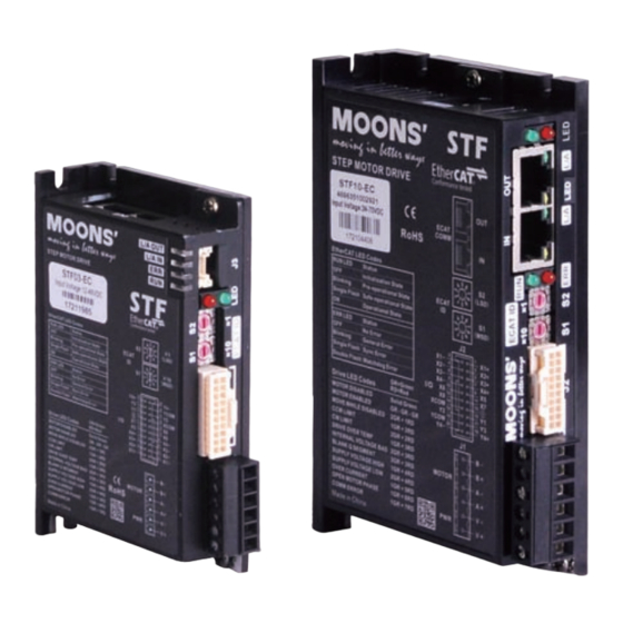
STF-EC
Stepper Motor Drive
Hardware Manual
STF03-EC
STF06-EC
SHANGHAI AMP & MOONS' AUTOMATION CO.,LTD.
STF05-EC
STF10-EC
Rev. 1.0
11/08/2017
Table of
Contents
Previous
Page
Next
Page
1
2
3
4
5
Advertisement
Table of Contents
Need help?
Do you have a question about the STF-EC Series and is the answer not in the manual?
Ask a question
Questions and answers
Related Manuals for Moons' STF-EC Series
DC Drives MOONS’ STB Series Hardware Manual
Stepper motor drive (25 pages)
DC Drives Moons' STF05-EC Hardware Manual
Stepper motor drive (28 pages)
DC Drives Moons' STF06-EC Hardware Manual
Stepper motor drive (28 pages)
DC Drives Moons' STF-D series Hardware Manual
Stepper motor drive (32 pages)
DC Drives Moons' Applied Motion Products STRAC8 Hardware Manual
Ac input step motor drive (21 pages)
DC Drives Moons' Applied Motion Products STRAC2 Hardware Manual
Ac input step motor drive (19 pages)
DC Drives Moons' STF-Multi axis Series Hardware Manual
(34 pages)
DC Drives Moons' SR4 User Manual
2 phase stepping motor drive (16 pages)
DC Drives Moons' SR8 User Manual
2 phase stepping motor drive (16 pages)
DC Drives Moons' SRAC2 User Manual
Ac input step motor drive (19 pages)
DC Drives Moons' SR4-Plus User Manual
2 phase step motor drive (18 pages)
DC Drives Moons' SRX04 User Manual
2 phase step motor drive (23 pages)
DC Drives Moons' SRX02 User Manual
2 phase step motor drive (21 pages)
DC Drives Moons' SSDC Multi-axis Series Hardware Manual
Step-servo system (47 pages)
DC Drives MOONS’ SR2-Plus Quick Setup Manual
Step motor drive (2 pages)
DC Drives Moons' MSST5-S User Manual
Step motor drive (33 pages)
This manual is also suitable for:
Stf03-ec
Stf05-ec
Stf06-ec
Stf10-ec
Table of Contents
Print
Rename the bookmark
Delete bookmark?
Delete from my manuals?
Login
Sign In
OR
Sign in with Facebook
Sign in with Google
Upload manual
Upload from disk
Upload from URL


Need help?
Do you have a question about the STF-EC Series and is the answer not in the manual?
Questions and answers