Table of Contents
Advertisement
Quick Links
Advertisement
Table of Contents

Related Manuals for Moons' SR4-Plus


Summary of Contents for Moons' SR4-Plus
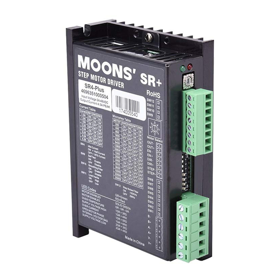
- Page 1 SR4-Plus 2 Phase Step Motor Drive User Manual Rev. 1.1 AMP & MOONS’ Automation...
-
Page 2: Table Of Contents
SR4-Plus User Manual Contents 1 Introduction .................. 3 1.1 Overview ....................3 1.2 Features .....................3 1.3 Block diagram ..................4 2 Mounting the Drive ..............4 3 Connections ................5 3.1 Connecting to the Power Supply ............5 3.2 Connecting to a Motor ...............5 3.3 Connecting to the Inputs ..............6... -
Page 3: Introduction
SR4-Plus User Manual 1 Introduction Thank you for selecting the MOONS’ SR4-Plus Motor Drive. We hope our commitment to perfor- mance, quality and economy will make a successful motion control project. 1.1 Overview The SR series drives are cost-effective, high performance 2 phase step drives. The design is based on advanced digital current control technology, and features high torque, low noise, and low vibration. -
Page 4: Block Diagram
2 Mounting the Drive The SR4-Plus Step Drive can be mounted on the wide or the narrow side of the chassis. If it is mounted on the wide side, M3 screws should be used through the four corner holes. For narrow side mounting applications, M3 screws can be used in the two side holes. -
Page 5: Connections
SR4-Plus User Manual 3 Connections To use the SR4-Plus Step Drive, the following items are needed: OUT- OUT+ Control signal • A power supply (24 - 48 VDC) DIR- DIR+ STEP- • Pulse & Direction signal STEP+ Switches for • A compatible step motor... -
Page 6: Connecting To The Inputs
3.3 Connecting to the Inputs 3.3.1 High Speed Digital Inputs The SR4-Plus drives include two high-speed inputs called STEP and DIR. They accept 5 to 24 volt single-ended or differential signals, up to 2 MHz. Typiclly these inputs connect to an external controller that provides step &... -
Page 7: The Enable (En) Digital Input
SR4-Plus User Manual 3.3.2 The Enable (EN) Digital Input The EN input enables or disables the drive amplifier. It is an optically isolated input that accepts a 5 to 24 volt single-ended or differential signal. The maximum voltage that can be applied to the input is 28V. -
Page 8: Programmable Output
SR4-Plus User Manual 3.3.3 Programmable Output The FAULT Output is optically isolated. The maximum collector current is 100mA, and the maxi- mum collector to emitter voltage is 30 volts. The output can be wired to sink or source current. When drive is working normally, the output is open. When the drive encounters an error, the output closes. -
Page 9: Switch Selection
Step Noise Filter 4.1 Running Current The output current of the SR4-Plus Step Drive is set by the SW1, SW2, and SW3 switches and can be changed as necessary. There are 8 settings available according to the ON/OFF combina- tion of the switches. -
Page 10: Microstepping
SR4-Plus User Manual 4.3 Microstepping The microstep resolution is set by the SW5, SW6, SW7 and SW8 switches. There are 16 settings. Microstep(steps/rev) 1600 3200 6400 12800 25600 1000 2000 4000 5000 8000 10000 20000 25000 4.4 Self Test Setting switch SW9 to ON after the drive is powered up will cause the drive to perform a self test move of 2 revolutions both CW and CCW at 1rps. -
Page 11: Step Smoothing Filter
Switch SW11 selects the load inertia. Set it to ON for high inertia applications and to OFF for low inertia applications. The load inertia selection can help the SR4-Plus drive to calculate the current control parameter, which is used in Anti-Resonance. If the load inertia is close to that of the motor rotor, select the low (OFF) setting. -
Page 12: Motor Selection
Each position of the 16-bit rotary switch selects a different motor, and automatically sets the configuration parameters in the drive. The SR4-Plus drive comes programmed with up to 8 typi- motors as factory defaults. Drives can be customized with specially selected motors when required. -
Page 13: Recommended Motors
SR4-Plus User Manual 5.1 Recommended motors 14HY Series 1.8° 4-M3 Parameters 20±0.5 40Max. 35.3Max. Depth 2.5Min. 26±0.1 15±0.2 2±0.2 AWG26 UL3266 A-A(2:1) Ø5-0.012 Parameters HOLDING ROTOR MOTOR LENGTH CURRENT OHMS WIRING TORQUE INERTIA WEIGHT PART# SHAFT DIAG LEADS N·m A/PHASE Ω/PHASE... - Page 14 SR4-Plus User Manual 23HS Series 1.8° 20.6 ±0.5 16 ±1 L Max. 56.4Max. +0.200 4-Ø5.1 47.14±0.20 15 ±0.2 15 ±0.2 1.6±0.2 4.8±0.3 AWG22 UL3266 C-C(2:1) D-D(2:1) Ø6.35-0.012 Ø6.35-0.012 These dimensions are for the double shaft models. For the single shaft models, ignore the shadow ( ) area.
-
Page 15: Error Codes
SR4-Plus User Manual 6 Error Codes The SR4-Plus Step Drive has one bicolor (red/green) LED to indicate status. When the motor is enabled, the green LED flashes slowly. When the green LED is solid, the motor is disabled. If the red LED flashes, an error has occurred. -
Page 16: Specifications
SR4-Plus User Manual 7.2 Specifications 7.2.1 Electrical Specifications Parameter Min. Typ. Max. Unit Power Supply Output Current (Peak) amps Step Frequency STEP Minimum Pulse Width Hi and Low DIR Minimum Pulse Width 62.5 Under Voltage Protection Over Voltage Protection STEP/DIR Input Signal Voltage... -
Page 17: Torque Curves
SR4-Plus User Manual 7.3 Torque Curves 14HYB401 17HD4452N Drive:SR4-Plus Drive:SR4-Plus Microstep:20000 steps/rev Microstep:20000 steps/rev Current:1.8A(Peak) Current:1.0A(Peak) Speed(rps) Speed(rps) 17HD2438N 17HD6426N Drive:SR4-Plus Drive:SR4-Plus Microstep:20000 steps/rev Microstep:20000 steps/rev Current:1.8A(Peak) Current:1.8A(Peak) Speed(rps) Speed(rps) 23HS0421 23HS2450 Drive:SR4-Plus Drive:SR4-Plus Microstep:20000 steps/rev Microstep:20000 steps/rev Current:4.5A(Peak) Current:4.5A(Peak)... -
Page 18: Contacting Moons
SR4-Plus User Manual 8 Contacting MOONS’ Service Center +86-400-820-9661 Headquarters No. 168 Mingjia Road Industrial Park North Minhang District Shanghai 201107, P.R. China Tel: +86(0)21-52634688 Fax: +86(0)21-62968682 E-mail: info@moons.com.cn MOONS' Industries (Europe) S.r.l. Via Torri Bianche n.1 20059 Vimercate(MB) Italy...
Need help?
Do you have a question about the SR4-Plus and is the answer not in the manual?
Questions and answers