Table of Contents
Advertisement
Quick Links
Advertisement
Table of Contents

Related Manuals for Moons' SRX02


Summary of Contents for Moons' SRX02
-
Page 2: Table Of Contents
SRX02 Hardware Manual Contents 1 Introduction ....................... 3 1.1 Ordering Part Number ................3 1.2 Features ....................3 2 Block Diagram ....................4 3 Technical Specifications ..................5 4 Mounting the Drive .................... 6 5 Connections ...................... 7 5.1 Connecting to the Power Supply ............7 5.2 Connecting the motor ................ -
Page 3: Introduction
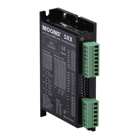
SRX02 Hardware Manual 1 Introduction Thank you for selecting the MOONS’ SRX02 Motor Drive. We hope our commitment to perfor- mance, quality and economy will make a successful motion control project. 1.1 Ordering Part Number Part Number Description SRX02-S Screw type terminal block connector Note: Please reference the picture of connector type on the first page. -
Page 4: Block Diagram
SRX02 Hardware Manual 2 Block Diagram SRX02 Block Diagram +12 to 48VDC 12-48 VDC External Power Supply 5Volt DC Power Supply Step Noise Filter Control Mode Smoothing Filter Step Res4 Self Test Step Res3 3.3VDC Step Res2 Internal Step Res1... -
Page 5: Technical Specifications
Amplifier Type Dual H-Bridge, 4 Quadrant Current Control PWM at 16KHz SRX02: 12-48 VDC Low Voltage Point: 11 VDC Over Voltage Point: 53 VDC Input Voltage SRX04: 24-48 VDC Low Voltage Point: 18 VDC Over Voltage Point: 53 VDC Range SRX08: 24-70 VDC Low Voltage Point: 18 VDC Over Voltage Point: 80 VDC SRX02: 0.3 ~ 2.2 A/phase(peak-of-sine) -
Page 6: Mounting The Drive
4 Mounting the Drive The SRX02 Step Drive can be mounted on the wide or the narrow side of the chassis. If it is mounted on the wide side, M3 screws should be used through the four corner holes. For narrow side mounting applications, M3 screws can be used in the two side holes. -
Page 9: Connecting The Motor
SRX02 Hardware Manual 5.2 Connecting the motor White White Green Brown Green Brown Yellow Yellow Gray Gray Pink Blue Blue Pink WARNING: Please power off the drive before connect the motor to the drive. Confirm the motor wind- ings don’t short with some other things. When the drive is power on, don’t disconnect the motor. -
Page 10: Connecting To The Input
5.3 Connecting to the Input 5.3.1 Pulse and Direction Input The SRX02 drives include two high-speed inputs called STEP and DIR. They accept 5 to 24 volt single-ended or differential signals, maximum 28 volt. These two inputs have input digital filter, 2MHz or 150KHz switch selectable. - Page 11 SRX02 Hardware Manual Inputs connection examples Common anode STEP+ Pulse signal STEP- DIR+ SRX02 Drive Direction DIR- signal Enable signal Common cathode Pulse signal STEP+ STEP- Direction DIR+ signal SRX02 Drive DIR- Enable signal Differential Pulse signal STEP+ STEP+ STEP-...
-
Page 12: Fault Output
SRX02 Hardware Manual 5.3.3 Fault Output The FAULT Output is optically isolated. The maximum collector current is 100mA, and the maxi- mumcollector to emitter voltage is 30 volts. The output can be wired to sink or source current. NOTE: When drive is working normally, the output is open. -
Page 13: Recommended Motor
SRX02 Hardware Manual 6 Recommended Motor Standard type step motor Holding Drive Current Rotor Length Mass Lead Mass Dielectric Torque Setting Range※ Inertia Model Features number Strength g.cm2 AM8HY2050-01N Single Shaft 29.5 0.02 0.3 - 0.5 0.04 AM8HY2050-02N Double Shaft... - Page 14 SRX02 Hardware Manual Encoder type motor Holding Drive Current Rotor Mass Length Mass Lead Torque Setting Range※ Inertia Model Features Dielectric number Strength g.cm2 AM17HD4452-E1000D External Encoder Motor 34.3 0.25 0.3 - 1.8 0.24 AM17HD2438-E1000D External Encoder Motor 39.8 0.3 - 1.8 0.29...
- Page 15 SRX02 Hardware Manual Torque Curves AM11HS1008 AM8HY4043 AM8HY2050 Microstep: 20000 steps/rev Microstep: 20000 steps/rev Microstep: 20000 steps/rev Current: 1.6A(Peak) Current: 0.5A(Peak) Current: 0.5A(Peak) 0.040 0.016 0.035 0.014 0.08 0.030 0.012 0.06 0.025 0.01 0.020 0.008 0.04 0.015 0.006 0.010 0.004 0.02...
-
Page 16: Drive Parameter Setting
Input Digital Filter 7.1 Running Current The output current of the SRX02 drive is set by the SW1, SW2, and SW3 switches. Generally speaking, the running current can be set as the rated current of the motor. If the system has request of heating, please try to reduce the running current. -
Page 17: Microstepping
SRX02 Hardware Manual 7.3 Microstepping The microstep resolution is set by the SW5, SW6, SW7 and SW8 switches. There are 16 settings. Microstep(steps/rev) 1600 3200 6400 12800 25600 1000 2000 4000 5000 8000 10000 20000 25000 7.4 Self Test Setting switch SW9 to ON after the drive is powered up will cause the drive to perform a self-test move of 2 revolutions both CW and CCW at 1rps. -
Page 18: Step Smoothing Filter
SRX02 Hardware Manual 7.5 Step Smoothing Filter Setting switch SW10 to ON select this function; setting it to OFF will disable it. Command signal smoothing can soften the effect of immediate changes in velocity and direction, making the motion of the motor less jerky. An added advantage is that it reduces wear on mechanical components. -
Page 19: Alarm Code
SRX02 Hardware Manual 8 Alarm Code Code Status Solid green no alarm, motor disabled Flashing green no alarm, motor enabled drive over temperature 3 red, 1 green internal voltage out of range 3 red, 2 green power supply over voltage... -
Page 20: Mechanical Outline
SRX02 Hardware Manual 9 Mechanical Outline SRX02-S 2.50 20.80 3.50 Unit: mm Rev.1.0 31/08/2020...
Need help?
Do you have a question about the SRX02 and is the answer not in the manual?
Questions and answers