Table of Contents
Advertisement
Quick Links
Advertisement
Table of Contents

Related Manuals for Moons' Applied Motion Products STRAC2


Summary of Contents for Moons' Applied Motion Products STRAC2
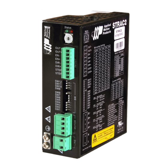
- Page 1 STRAC2 AC Input Step Motor Drive Hardware Manual Applied Motion Products, Inc.
-
Page 2: Table Of Contents
920-0118 Rev B STRAC2 Hardware Manual 03/26/21 Table of Contents 1 Introduction ...............................3 1.1 Features................................3 1.2 Block diagram ..............................4 2 Mounting the Drive ............................4 3 Connections ..............................5 3.1 Connecting to Power ............................6 3.3 Connecting the Inputs and Outputs ........................8 3.3.1 Step &... -
Page 3: Introduction
920-0118 Rev B STRAC2 Hardware Manual 03/26/21 1 Introduction Thank you for selecting the Applied Motion Products’ STRAC2 Step Motor Drive. The STRAC2 series AC input drives are based on advanced digital current control technology and provide high torque, low noise and low vibration. Many of the operational paramteres are switch selectable. -
Page 4: Block Diagram
920-0118 Rev B STRAC2 Hardware Manual 03/26/21 1.2 Block diagram 90~135VAC AC Input 135~240VAC STRAC2 switching Block Diagram Step Res 1 Step Res 2 Step Res 3 Step Res 4 Current Set 1 3.3V Current Set 2 Voltage Current Set 3 Det. -
Page 5: Connections
920-0118 Rev B STRAC2 Hardware Manual 03/26/21 3 Connections To use the STRAC2 Step Drive, the following items are needed: • Universal AC input of 90 to 240 VAC • Pulse & Direction signal • A compatible step motor • AC input voltage must be selected by switch... -
Page 6: Connecting To Power
920-0118 Rev B STRAC2 Hardware Manual 03/26/21 3.1 Connecting to Power Use the supplied connector to connect to the AC supply according to the diagram below. Use 16 AWG wire for Line (L) and Neutral (N). Use 14 AWG for Earth Ground (G). AC input voltage must be selected by switch.Check input voltage avoiding damage before power on! Input Voltage between 90Vac to 135Vac: Set the switch on 115V Status Input Voltage between 135VAC to 240VAC: Set the switch on 230V Status... - Page 7 920-0118 Rev B STRAC2 Hardware Manual 03/26/21 Connecting Other Motors If you do want to connect other motors , here is some information that will help Four lead motors can only be connected one way. Please follow the sketch at the right. lead motor A–...
-
Page 8: Connecting The Inputs And Outputs
920-0118 Rev B STRAC2 Hardware Manual 03/26/21 3.3 Connecting the Inputs and Outputs 3.3.1 Step & Direction Inputs The STRAC2 Step Drive has two high speed optically isolated inputs called STEP and DIR. They accept 5 to 24 volt single-ended or differential signals, up to 2MHz. -
Page 9: Input
920-0118 Rev B STRAC2 Hardware Manual 03/26/21 3.3.2 EN input The EN input enables or disables the drive amplifier. It is an optically isolated input that accepts a 5 to 24 volt single-ended or differential signal. The maximum voltage that can be applied to the input is 28V. When EN input is closed, the driver amplifier is deactivated, all the MOSFETs will shut down, and the motor will be free. -
Page 10: Fault Output
920-0118 Rev B STRAC2 Hardware Manual 03/26/21 3.3.3 Fault Output The FAULT Output is optically isolated. The maximum collector current is 100mA, and the maximum collector to emitter voltage is 30 volts. The output can be wired to sink or source current. When drive is working normally, the output is open. -
Page 11: Switch Selection
920-0118 Rev B STRAC2 Hardware Manual 03/26/21 4 Switch Selection Many of the operational parameters of the STRAC2 can be set or changed by position switches - either by a single switch or a combination of ON/OFF settings of 2 or more switches. Idle Current Microstepping Running Current... -
Page 12: Running Current
920-0118 Rev B STRAC2 Hardware Manual 03/26/21 4.2 Running Current The output current is set by the SW5, SW6 and SW7 switches. There are 8 settings. NOTE: Drive’s running current will be limited by the lower value between motor selection rotary switch or the dip current switch Current (Peak) 0.6A... -
Page 13: Step Smoothing Filter
920-0118 Rev B STRAC2 Hardware Manual 03/26/21 4.6 Step Smoothing Filter Command signal smoothing can soften the effect of immediate changes in velocity and direction, making the motion of the motor less jerky. An added advantage is that it can reduce the wear on mechanical components. SW11 selects this function - ON enables it, OFF disables it. -
Page 14: Motor Selection
920-0118 Rev B STRAC2 Hardware Manual 03/26/21 5 Motor selection Each position of the 16-bit rotary switch selects a different motor, and automatically sets the configuration parameters in the drive. The STRAC2 drive comes programmed with up to 16 typical motors as factory defaults. Drives can be customized with specially selected motors when required. -
Page 15: Recommended Motors
920-0118 Rev B STRAC2 Hardware Manual 03/26/21 5.1 Recommended motors Model Number Connection Length Holding Torque Series Current Parallel Current Rotor Inertia HT23-552 Series 1.71 84.4 0.71 1.41 0.0017 HT23-553 Series 2.17 0.71 1.41 0.00425 HT23-554 Series 3.05 0.71 1.41 0.0068 HT34-495/695 Series... -
Page 16: Error Codes
920-0118 Rev B STRAC2 Hardware Manual 03/26/21 6 Error Codes The STRAC2 Drive has two LEDs to indicate status. When the motor is enabled the green LED flashes slowly, when the green LED is solid the motor is disabled. If the red LED flashes, an error has occurred. Errors are indicated by combinations of red and green flashes as shown below: Code Error... -
Page 17: Reference Materials
920-0118 Rev B STRAC2 Hardware Manual 03/26/21 7 Reference Materials 7.1 Mechanical Outline 47.5 10.5 Status SRAC STEP MOTOR DRIVE RoHS Motor Select OUT - Serial No Part No OUT+ EN - Microstep Table Current Table OUT - OUT+ MSTEP Current DIR - 0.4A... -
Page 18: Specifications
920-0118 Rev B STRAC2 Hardware Manual 03/26/21 7.2 Specifications 7.2.1 Electrical Specifications Electrical Specifications Parameter Min. Typ. Max. Unit Power Supply Output Current (Peak) Step Frequency STEP Minimum Pulse Width Hi and Low DIR Minimum Pulse Width 62.5 Under Voltage Protection 75*/135* Over Voltage Protection 145*/295*... -
Page 19: Contacting Applied Motion Products
920-0118 Rev B STRAC2 Hardware Manual 03/26/21 8 Contacting Applied Motion Products 404 Westridge Dr. Watsonville, CA 95076, USA 1-800-525-1609 www.applied-motion.com...
Need help?
Do you have a question about the Applied Motion Products STRAC2 and is the answer not in the manual?
Questions and answers