Table of Contents
Advertisement
Quick Links
Advertisement
Table of Contents

Related Manuals for Crestron CNTV


Summary of Contents for Crestron CNTV
-
Page 3: Table Of Contents
CRESTRON CNTV DESCRIPTION... 1 Functional Description... 1 Physical Description... 1 LEADING SPECIFICATIONS ... 1 CONTROLS AND INDICATORS... 2 Controls... 2 Indicators... 3 IR ... 3 MESSAGE... 3 READY ... 3 T and R... 3 INSTALLATION/SETUP ... 3 Optional Equipment... 3 Identity Code ... -
Page 5: Description
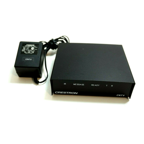
Physical Description The CNTV is housed in a black enclosure with silk-screened labels on the front and back of the case. On the front, there are five red LEDs for indicating the current status of the unit. All connections are made on the back of the unit. -
Page 6: Controls And Indicators
CONTROLS AND INDICATORS: Controls The CNTV has an IR receiver on the front-right side, located above the CNTV label. Verify that the receiver is in a line-of-sight path and unobstructed. The LED flashes when IR is received, confirming a good line-of- sight path. -
Page 7: Indicators
Optional Equipment Due to variations in installation requirements, not all possible peripheral pieces of equipment are supplied with the CNTV. Table 2 provides a list of all optional equipment that can be used in conjunction with the CNTV. Table 2. Optional Equipment... -
Page 8: Identity Code
If the CNTV ID CODE needs to be altered, it can be set from a PC via CNTV SETUP menus. Refer to the Appendix in this guide for details that describe the method of setting the CNTV ID CODE. -
Page 11: Ir Probe Placement
Crestron recommends that wall jacks with an RJ11 (6-6) receptacle be located in the room with a CNTV. Use a telephone cable of appropriate length to connect the CNTV to the wall jack. Wire a Cresnet cable to the four terminals at the rear of the wall jack. -
Page 13: Programming
Crestron CNTV Worksheet. This worksheet permits Crestron to prepare a specific configuration file based on the intended use of the CNTV. Append this file to the overall control system program in SIMPL Windows. For more details regarding programming the CNTV, consult a Crestron technical representative. -
Page 14: Further Inquiries
T and R LEDs are not illuminated. FURTHER INQUIRIES: If after reviewing this Operations Guide for the CNTV, you cannot locate specific information or have questions, please take advantage of Crestron's award winning technical support team by calling: In the US and Canada, call Crestron's corporate headquarters at 1-888-CRESTRON [1-888-273-7876] or 1-201-767-3400. -
Page 15: Appendix
CNTV setup parameters and diagnostic tools are accessible via a PC. A diagnostic cable, illustrated in figure 2, is used to connect the PC to COM1 port of the CNTV for setup and diagnostic purposes. Connect a computer running a terminal emulator, such as Windows Terminal (included with Windows ProComm Plus, or Telix. -
Page 16: Mrmt11 Setup Menus
The MRMT11 SETUP menus can be accessed only after connecting the communication port of the PC (specified in the previous section) to the COM1 port of the CNTV with the diagnostic cable and applying power. Refer to the Preparation for Use section for details that describe CNTV power connections. -
Page 17: Downloading Tasks
0 - Return to previous menu To display the current CNTV ID CODE setting, depress "1". To enter a new CNTV ID CODE, depress "2", enter the new ID CODE, and depress "Enter". The program responds by displaying the ID CODE as verification. - Page 18 (not supplied). Figure 3 describes the loop materials and how to make one. If the CNTV is driving more than one TV, an additional MRIRP must be ordered. To initiate the Power Sensor Test for the power sense (PWR SENSE) 1 port, depress "1". To initiate the Power Sensor Test for the power sense (PWR SENSE) 2 port, depress "2".
-
Page 19: Test Digital Inputs
CRESTRON CNTV Test Digital Inputs Depressing "1" from the MRMT11 VersiPort Test Menu opens the MRMT11 VersiPort Digital Input Test Menu which appears on the screen as six lines of text. MRMT11 VersiPort Digital Input Test Menu 1 - VersiPort 1... - Page 20 CRESTRON CNTV MRMT11 VersiPort Set Analog Threshold Menu 1 - VersiPort 1 2 - VersiPort 2 3 - VersiPort 3 4 - VersiPort 4 0 - Return to previous menu To set the VersiPort Analog Threshold for each pin in the DIGITAL IN/OUT port, depress the corresponding menu number.
-
Page 21: Return And Warranty Policies
CRESTRON CNTV RETURN AND WARRANTY POLICIES: Merchandise Returns / Repair Service 1. No merchandise may be returned for credit, exchange, or service without prior authorization from CRESTRON. To obtain warranty service for CRESTRON products, contact the factory and request an RMA (Return Merchandise Authorization) number.
Need help?
Do you have a question about the CNTV and is the answer not in the manual?
Questions and answers