Table of Contents
Advertisement
Quick Links
FT2A-CHGR-USBA/C
USB Rapid Charging Module for FT2-ELEC Series
Installation Guide
Description
The Crestron
FT2A-CHGR-USBA/C module provides one USB Type-A port and one
®
USB Type-C™ port for charging USB devices within an electrically-powered FT2
FlipTop™ system.
Additional Resources
Visit the product page on the Crestron website (www.crestron.com)
for additional information and the latest rmware updates. Use a QR
reader application on your mobile device to scan the QR image.
Overview
Each FT2A-CHGR-USBA/C module provides one USB Type-A port and one USB Type-C
port for charging USB devices via cables with USB-A connectors and
USB-C™ connectors, respectively. The charging behavior for an FT2A-CHGR-USBA/C
module differs depending on the type(s) of USB connections made:
• If a USB device is connected to the USB-A port and the USB-C port is not used, full
12 W charging rapidly charges the device.
• If a USB device is connected to the USB-C port and the USB-A port is not used, full
USB-C charging rapidly charges the device at up to 32.5 W maximum power.
NOTE: The rapidity of the USB-C charge varies depending on the device and its
power level.
• If devices are connected to both the USB-A port and the USB-C port, the USB-C
device rapidly charges while the USB-A device charges at a 2.5 W limit.
The FT2A-CHGR-USBA/C module is 0.98" x 1.97" (25 x 50 mm), and it requires one empty
module space in the FT2-ELEC for installation. The FT2A-CHGR-USBA/C module also
features a backlit LED icon that lights when the module is connected to an FT2 power bus.
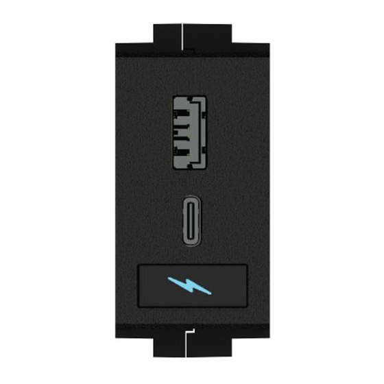
FT2A-CHGR-USBA/C Diagram
USB Type-C port
USB Type-A port
LED icon
Installation
NOTE: The FT2A-CHGR-USBA/C module is only compatible with the FT2-ELEC series.
NOTE: No more that two FT2A-CHGR-USBA/C modules can be installed in an
FT2-ELEC:
• If two FT2A-CHGR-USBA/C modules are installed in an FT2-ELEC, each module
must be positioned in a different module row.
• Each module row containing a FT2A-CHGR-USBA/C module must be powered by
its own power supply. For more information on installing power supplies, refer to the
FT2-ELEC DO Guide (Doc. 8216) at www.crestron.com/manuals.
Use the following procedure to install the FT2A-CHGR-USBA/C module into an FT2-ELEC
assembly. If the FT2A-CHGR-USBA/C module is being installed as part of a new
FT2-ELEC installation, skip ahead to step 3.
1. Remove the magnetic bezel from the FT2-ELEC assembly by grasping the inside of
the bezel and by rmly pulling it up and away from the assembly until the magnetic
hold is broken.
2. Unscrew and remove the two locking bars on either side of the module row needed
for installation. For example, if installing the FT2-CHGR-USBA/C module in the
bottom row of an FT2-700, remove the middle and bottom locking bars.
Removing the Locking Bars
Locking bars (3)
3. Orient the module so that the module's LED icon is facing toward the front of the
FT2-ELEC assembly as shown in the following illustration.
Positioning the FT2A-CHGR-USBA/C
FT2A-CHGR-USBA/C
Retractable lid
(located in rear
of assembly)
Front of
assembly
Advertisement
Table of Contents

Related Manuals for Crestron FT2A-CHGR-USBA/C


Summary of Contents for Crestron FT2A-CHGR-USBA/C
- Page 1 USB-A device charges at a 2.5 W limit. The FT2A-CHGR-USBA/C module is 0.98" x 1.97" (25 x 50 mm), and it requires one empty module space in the FT2-ELEC for installation. The FT2A-CHGR-USBA/C module also features a backlit LED icon that lights when the module is connected to an FT2 power bus.
- Page 2 NOTE: This equipment has been tested and found to comply with the limits for a Class B digital marks and names or their products. Crestron disclaims any proprietary interest in the marks and device, pursuant to part 15 of the FCC Rules. These limits are designed to provide reasonable names of others.
Need help?
Do you have a question about the FT2A-CHGR-USBA/C and is the answer not in the manual?
Questions and answers