Table of Contents
Advertisement
Quick Links
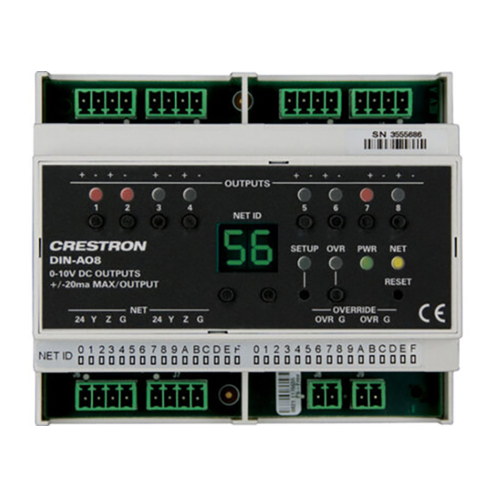
DIN-AO8
DIN Rail Analog Output Module
Installation & Operation Guide
Description
The Crestron
DIN-AO8 is a DIN rail-mounted automation control module that provides
®
eight analog output ports for interfacing with third-party lighting and heating and cooling
systems.
Additional Resources
Visit the product page on the Crestron website (www.crestron.com)
for additional information and the latest rmware updates. Use a QR
reader application on your mobile device to scan the QR image.
Installation
WARNING: To avoid re, shock, or death, turn off the power at the circuit breaker or
fuse and test that the power is off before wiring!
NOTES: Observe the following points:
• This product must be installed and used in accordance with appropriate electrical
codes and regulations.
• This product must be installed by a quali ed electrician.
1. Place the top of the DIN-AO8's rail mount over the top of the DIN rail.
2. Tilt the bottom of the DIN-AO8 toward the DIN rail until it snaps into place.
NOTE: When mounting DIN rail products, it may be necessary to use a at-head
screwdriver to pull the DIN rail release tab while snapping the device onto the DIN rail.
NOTE: Certain third-party DIN cabinets provide space for an informational label
between each DIN rail row. Crestron's Engraver software (version 4.0 or later) can
generate appropriate labels for all Crestron DIN rail products.
DIN Rail
Release
NOTE: To remove the DIN-AO8 from the DIN rail, use a small, at object (i.e., a
at-head screwdriver) to pull the DIN rail release and tilt the bottom of the DIN-AO8
away from the DIN rail.
Hardware Hookup
Make the necessary connections. Apply power after all connections have been made.
WARNING: Prior to connecting the device, turn off power at the circuit breaker. Failure
to do so may result in serious personal injury or damage to the device. Restore power
after all connections have been made.
CAUTION: Connecting this device to the wrong type of load or short-circuiting the load
can cause severe product damage. Each load should be tested to identify a short-circuit
condition prior to wiring the load to the module.
NOTE: Use copper wire only.
NOTE: Each switch leg of the DIN-AO8 may be fed from a separate circuit breaker.
When making OUTPUTS, NET, and OVERRIDE connections, strip the ends of the wires
approximately 7/16 in (11 mm). Use care to avoid nicking the conductors. Tighten the
connector to 5 in-lb (0.5 to 0.6 N-m). The wire gauge should be 14 to 26 AWG.
When making power connections to the DIN-AO8, use a Crestron power supply.
Hardware Connections for the DIN-AO8
DIN-AO8
Top
DIN Rail (Not
Supplied)
To Control System and
Other Cresnet Devices
OUTPUTS:
To Devices with
Analog Inputs
NET:
OVERRIDE:
From Device Providing
Override Signal and to Other
Devices Receiving Override
Signal
Advertisement
Table of Contents

Related Manuals for Crestron DIN-AO8


Summary of Contents for Crestron DIN-AO8
- Page 1 • This product must be installed by a quali ed electrician. 1. Place the top of the DIN-AO8’s rail mount over the top of the DIN rail. 2. Tilt the bottom of the DIN-AO8 toward the DIN rail until it snaps into place.
- Page 2 The Override mode overrides the control system program and sets all of the output levels to the saved override values. For instructions on saving override levels, refer to “Establish The Net ID of the DIN-AO8 has been factory set to 88. The Net IDs of all devices in the Override Mode Levels.”...
Need help?
Do you have a question about the DIN-AO8 and is the answer not in the manual?
Questions and answers