
Subscribe to Our Youtube Channel
Related Manuals for Wren TOWER UNIT 2070


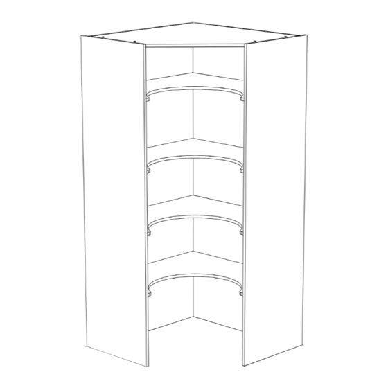
Summary of Contents for Wren TOWER UNIT 2070
- Page 1 TOWER UNIT 2070 & 2250 Walk In Tower Assembly Guide 2070 - 2250 1 Door 70/30 Door 50/50 Door For Internal Use: FI.WR.INS.014_WKIN0062_Walkin_Tower_Guide_Rev15...
-
Page 2: Before You Start
TOWER UNIT 2070 & 2250 Walk In Tower Assembly Guide BEFORE YOU START INSTALLATION SHOULD BE PERFORMED BY A COMPETENT PERSON ONLY. THIS PRODUCT COULD BE DANGEROUS IF INCORRECTLY INSTALLED Screws and fixings for attaching to walls are not provided as these vary depending on materials and construction. - Page 3 TOWER UNIT 2070 & 2250 Walk In Tower Assembly Guide Panel A Panel B Panel C Panel D x1 End Panel x1 End Panel x1 Back Panel x1 Back Panel Left Hand Right Hand Left Hand Right Hand Option 70/30 Option 50/50 Option...
- Page 4 TOWER UNIT 2070 & 2250 Walk In Tower Assembly Guide (F) x40 (W) x20 (K) x36 (L) x12 (H) x20 Wooden Dowel Cam Dowel 45mm Screws 15mm Screws Cam Lock (M) x8 Fixing Plate (U) Door Buffer L Bracket LGE Cover Cap Hinge Hinge Mounting Plate...
- Page 5 TOWER UNIT 2070 & 2250 Walk In Tower Assembly Guide Step 1. Seat cam dowel (W) into holes in end panel (A) as shown. For Internal Use: FI.WR.INS.014_WKIN0062_Walkin_Tower_Guide_Rev15 Page 3...
- Page 6 TOWER UNIT 2070 & 2250 Walk In Tower Assembly Guide Step 2. Seat dowel (F) into holes in end panel (A) as shown. For Internal Use: FI.WR.INS.014_WKIN0062_Walkin_Tower_Guide_Rev15 Page 4...
- Page 7 TOWER UNIT 2070 & 2250 Walk In Tower Assembly Guide Step 3. Attach panels (sM) and (sE) to end panel (A), using cam dowel (W) and dowels (F) in positions as shown. Panel (sE) cam holes to face the outside of the unit. Panels (sM) cam holes to face downwards.
- Page 8 TOWER UNIT 2070 & 2250 Walk In Tower Assembly Guide Step 5. Seat 20 x dowels (F) into holes in panels (sM) and (sE) as shown. For Internal Use: FI.WR.INS.014_WKIN0062_Walkin_Tower_Guide_Rev15 Page 6...
- Page 9 TOWER UNIT 2070 & 2250 Walk In Tower Assembly Guide Step 6. Slide back panel (C) into groove of end panel (A). Also insert dowels (F) from panels (sM) and (sE) into the required holes in back panel (C). Once back panel (C) is in position, ensure the panel is flush & square with bottom of end panel (A) and secure in place with 15 x 45mm screws (K) through panel (C) into panels (sM) and (sE).
- Page 10 TOWER UNIT 2070 & 2250 Walk In Tower Assembly Guide Step 7. Hand tighten all cam locks (H), this will expand cam dowels (W) and tighten the unit together. Step 8. Secure back panel (C) to end panel (A) at the bottom using 1 x L bracket LGE as shown. Secure the L Bracket LGE in place with 4 x 15mm screws (L).
- Page 11 TOWER UNIT 2070 & 2250 Walk In Tower Assembly Guide Step 9. Seat cam dowel (W) into holes in end panel (B) as shown. For Internal Use: FI.WR.INS.014_WKIN0062_Walkin_Tower_Guide_Rev15 Page 9...
- Page 12 TOWER UNIT 2070 & 2250 Walk In Tower Assembly Guide Step 10. Seat dowel (F) into holes in end panel (B) as shown. For Internal Use: FI.WR.INS.014_WKIN0062_Walkin_Tower_Guide_Rev15 Page 10...
- Page 13 TOWER UNIT 2070 & 2250 Walk In Tower Assembly Guide Step 11. Attach end panel (B) to panels (sM) and (sE) using cam dowel (W) and dowels (F) in positions as shown. Step 12. Insert cam locks (H). Do NOT tighten until Step 17. For Internal Use: FI.WR.INS.014_WKIN0062_Walkin_Tower_Guide_Rev15 Page 11...
- Page 14 TOWER UNIT 2070 & 2250 Walk In Tower Assembly Guide Step 13. Slide back panel (D) into groove of end panel (B). Also insert dowels (F) from panels (sM) and (sE) into the required holes in back panel (D). Once back panel (D) is in position, ensure the panel is flush & square with bottom of end panel (B) and secure in place with 21 x 45mm screws (K) through panel (D) into panels (sM) and (sE).
- Page 15 TOWER UNIT 2070 & 2250 Walk In Tower Assembly Guide Step 15. Hand tighten all cam locks (H), this will expand cam dowels (W) and tighten the unit together. Step 15. Ensure that the tower is positioned correctly and level. Secure the tower to the wall using 2 x L brackets LGE.
- Page 16 TOWER UNIT 2070 & 2250 Walk In Tower Assembly Guide 2070 Step 19. Attach hinge plates onto end panel (A) or (B) to suit as shown using screws already positioned within the hinge plate. Hinge side or sides to be mounted in accordance to Customer Specific Kitchen Plan. 2070 - 70/30 2070 - 50/50 &...
- Page 17 TOWER UNIT 2070 & 2250 Walk In Tower Assembly Guide 2250 Step 19. Attach hinge plates onto end panel (A) or (B) to suit as shown using screws already positioned within the hinge plate. Hinge side or sides to be mounted in accordance to Customer Specific Kitchen Plan. 2250 - 70/30 2250 - 50/50 HINGE POSITION...
- Page 18 TOWER UNIT 2070 & 2250 Walk In Tower Assembly Guide 2250 Step 19. Attach hinge plates onto end panel (A) or (B) to suit as shown using screws already positioned within the hinge plate. Hinge side or sides to be mounted in accordance to Customer Specific Kitchen Plan. 2250 - 1 Door HINGE POSITION 2156mm...
- Page 19 TOWER UNIT 2070 & 2250 Walk In Tower Assembly Guide Hinge Attachment and Adjustment Doors supplied in accordance to customer specific kitchen plan Step 1. Insert hinges into frontal hinge holes provided, secure hinges with the 2 50/50 1 DOOR x screws and hinge dowels already Hinge dowels &...
- Page 20 TOWER UNIT 2070 & 2250 Walk In Tower Assembly Guide Step 4. Adjust hinges to suit, using the highlighted screws shown. Step 5. Fit cover caps to hinges and adjust soft-close to suit. The top and bottom hinges MUST be adjusted to the SAME STRENGTH. For Internal Use: FI.WR.INS.014_WKIN0062_Walkin_Tower_Guide_Rev15 Page 18...
Need help?
Do you have a question about the TOWER UNIT 2070 and is the answer not in the manual?
Questions and answers