
Related Manuals for Wren Vogue BASE UNIT 150


Summary of Contents for Wren Vogue BASE UNIT 150
- Page 1 BASE UNIT 150 - 300, Pull Out Assembly Guide 150, Base Pull Out 300, Base Pull Out IMAGES SHOWN FOR ILLUSTRATION PURPOSES For Internal Use: FI.WR.INS.029_WKIN00101_BASE_150_300_PullOut_Rev7...
- Page 2 BASE UNIT 150 - 300, Pull Out Assembly Guide BEFORE YOU START INSTALLATION SHOULD BE PERFORMED BY A COMPETENT PERSON ONLY. THIS PRODUCT COULD BE DANGEROUS IF INCORRECTLY INSTALLED NOT to be used with CAM LOCK Page 2 For Internal Use: FI.WR.INS.029_WKIN00101_BASE_150_300_PullOut_Rev7...
- Page 3 BASE UNIT 150 - 300, Pull Out Assembly Guide Panel A Panel C Panel B Frontal x2 End Panel x2 Fixed Shelf x1 Back Panel x1 Front Panel (Packed Separetly) Page 3 For Internal Use: FI.WR.INS.029_WKIN00101_BASE_150_300_PullOut_Rev7...
- Page 4 BASE UNIT 150 - 300, Pull Out Assembly Guide (F) x8 (L) x20 (X) x8 (K) x6 (G) x8 (H) x8 (J) x6 30mm Wooden 15mm 19mm Cam Dowel Cam Lock 16mm Dowel Screw Screw Screw Screw (Expanding) L Bracket (M) x4 (N) x1 Cover Cap...
- Page 5 BASE UNIT 150 - 300, Pull Out Assembly Guide Step 1. Seat dowels (F) into holes in both end panels (A) as shown. Page 5 For Internal Use: FI.WR.INS.029_WKIN00101_BASE_150_300_PullOut_Rev7...
- Page 6 BASE UNIT 150 - 300, Pull Out Assembly Guide Step 2. Seat expanding cam dowels (G) into holes in both end panels (A) as shown. Page 6 For Internal Use: FI.WR.INS.029_WKIN00101_BASE_150_300_PullOut_Rev7...
- Page 7 BASE UNIT 150 - 300, Pull Out Assembly Guide For ease of installation, it is recommended that the pull out mechanism for 150 wide unit is installed before the unit is assembled together. Step 3. Attach panels (C) to panels (A), using expanding cam dowels (G), and wooden dowels (F) in positions as shown.
- Page 8 BASE UNIT 150 - 300, Pull Out Assembly Guide Step 4. Slide back panel (B) into groove of end panels (A). Once back panel (B) is in position, ensure the panel is flush & square with bottom of end panels. Page 8 For Internal Use: FI.WR.INS.029_WKIN00101_BASE_150_300_PullOut_Rev7...
- Page 9 BASE UNIT 150 - 300, Pull Out Assembly Guide Step 5. Insert cam locks (H) and hand tighten them, this will expand cam dowels (G) and tighten the unit together. Do not use power tools with cam lock (H) Page 9 For Internal Use: FI.WR.INS.029_WKIN00101_BASE_150_300_PullOut_Rev7...
- Page 10 BASE UNIT 150 - 300, Pull Out Assembly Guide Step 6. Ensure the unit is square. Secure back panel (B) with 2 x 30mm screws (K) at the top & bottom of back panel (B) into both fixed shelves (C), as shown. Ensure you screw into the centres of the fixed shelves (C) (9mm from the edge).
- Page 11 BASE UNIT 150 - 300, Pull Out Assembly Guide Step 7. Position legs as shown on the diagram below. Ensure legs are rotated to also provide support to the end panels (A). Once positioned, secure each of the legs into place with 4 x 15mm screws (L) per leg.
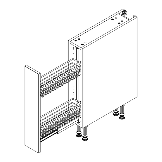
- Page 12 BASE UNIT 150 - 300, Pull Out Assembly Guide Pull Out Pack Please refer to separate installation instructions included with your pull out contents. IMAGES SHOWN FOR ILLUSTRATION PURPOSES Pull out instruction. For Step 1, 2 in pull out instructions use 16mm screws. For Step 4 use 19mm screws. Page 12 For Internal Use: FI.WR.INS.029_WKIN00101_BASE_150_300_PullOut_Rev7...
- Page 13 BASE UNIT 150 - 300, Pull Out Assembly Guide Screws for attaching to walls and worktops are not provided as these vary depending on materials, thickness and construction. Ensure appropriate fixings for wall and worktop construction are used. Please refer to the specialist worktop supplier if these are required for solid surface worktops. Step 8.
- Page 14 BASE UNIT 150 - 300, Pull Out Assembly Guide Step 10. Screw into any adjacent units using the 30mm screws (K) provided. Screw at the top and bottom of both sides of the unit, place a cover cap (M) to the screw head to conceal it.
- Page 15 BASE UNIT 150 - 300, Pull Out Assembly Guide For Internal Use: FI.WR.INS.029_WKIN00101_BASE_150_300_PullOut_Rev7...
Need help?
Do you have a question about the Vogue BASE UNIT 150 and is the answer not in the manual?
Questions and answers