Table of Contents
Advertisement
Quick Links
Advertisement
Table of Contents

Related Manuals for Effekta THOR RM


Summary of Contents for Effekta THOR RM
- Page 1 Uninterruptible Power Systems 10~50kVA Operation Manual...
- Page 2 All rights reserved. The information in this document is subject to change without notice. Publish statement Thank you for purchasing this series UPS. This series UPS is an intelligent, three phase in Three phase out, high frequency online UPS designed by our R&D team who is with years of designing experiences on UPS. With excellent electrical performance, perfect intelligent monitoring and network functions, smart appearance, complying with EMC and safety standards, The UPS meets the world’s advanced level.
-
Page 3: Table Of Contents
Contents Safety .............................. 2 1.1 Safety notes ..........................2 1.2 Symbols used in this guide ....................2 Main Features ..........................3 2.1 Summarization ........................3 2.2 Functions and Features ......................3 Installation ............................4 3.1 Sub Rack UPS ......................... 4 3.2 Tower UPS .......................... -
Page 4: Safety
Safety Important safety instructions - Save these instructions There exists dangerous voltage and high temperature inside the UPS. During the installation, operation and maintenance, please abide the local safety instructions and relative laws, otherwise it will result in personnel injury or equipment damage. Safety instructions in this manual act as a supplementary for the local safety instructions. -
Page 5: Main Features
Main Features 2.1 Summarization This series UPS is a kind of three-in-three-out high frequency online UPS. The UPS can solve most of the power supply problems, such as blackout, over-voltage, under-voltage, voltage sudden drop, oscillating of decreasing extent, high voltage pulse, voltage fluctuation, surge, inrush current, harmonic distortion (THD), noise interference, frequency fluctuation, etc.. -
Page 6: Installation
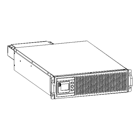
Installation 3.1 Sub Rack UPS 3.1.1 Appearance of UPS 10/15/20/25/30kVA 40/50kVA 3.1.2 Installation Adjust the length of the rails according to the following figure according to the distance of the cabinet and fix the rails. Fix the rails to the cabinet. 10/15/20/25/30kVA 40/50kVA... -
Page 7: Tower Ups
After installing the rails, install the floating screw according to the front panel of the UPS, then insert the UPS into the cabinet on the rails and fix the screws. 10/15/20/25/30kVA 40/50kVA 3.2 Tower UPS 3.2.1 Appearance of UPS 10/15/20/25/30kVA 40/50kVA 3.2.2 Installation... -
Page 8: Cabinet Outlook
Remove the fix handles of the UPS 10/15/20/25/30kVA 40/50kVA Assemb the bracket, according to the size of the UPS, and then the UPS can be directly placed on the bracket. 10/15/20/25/30kVA 40/50kVA 3.3 Cabinet Outlook... - Page 9 10/15/20/25/30kVA: Front View Rear View (1) LCD panel (2) Backfeed protection port (3) MAINTAIN-AUXSWS port (4) Output breaker aux contactor (5) USB port (6) Cold-start button (7) Terminal block for Input, output & battery (8) Dry contact port (9) Parallel port 1 (10) Parallel port 2 (11) EPO port (12) Temperature sensor port (for NTC)
- Page 10 40/50kVA: Front View Rear View LCD panel EPO port Cold-start button Output breaker aux contactor Intelligent Slot (SNMP card/ Relay card) Parallel port 1&2 MAINTAIN-AUXSWS port (Need to set the LBS port LCD disable to enable when use the port) and REPO port Optional port (Port for backfeed protection, (10) BAT_SW : detect battery switch status...
-
Page 11: Lcd Control Panel
3.3 LCD control panel LCD control panel introduction (1)LED(from top to bottom: ―alarm‖, ―bypass‖, ―battery‖, ―inverter‖) (2)LCD display (3)scroll button (4)Off button (5)On button 3.4 Installation notes Note: Consider for the convenience of operation and maintenance, the space in front and back of the cabinet should be left at least 100cm and 80cm respectively when installing the cabinet. -
Page 12: External Protective Devices
Altitude 1500 2000 2500 3000 3500 4000 4500 5000 Load 100% coefficient The UPS cooling is depending on fan, so it should be kept in good air ventilation area. ◆ There are many ventilation holes on the front and rear, so they should not be blocked by any exotic obstacles. - Page 13 When selecting, connecting, and routing power cables, follow local safety regulations and ◆ rules. If external conditions such as cable layout or ambient temperatures change, perform ◆ verification in accordance with the IEC-60364-5-52 or local regulations. If the rated voltage is 400 V, multiply the currents by 0.95. If the rated voltage is 415 V, ◆...
-
Page 14: Power Cable Connect
3.6.3 Recommended input front-end and output back-end circuit breakers Mains input Bypass input Maintenance Output circuit Battery circuit Model circuit breaker circuit breaker circuit breaker breaker breaker 10kVA 20A 3P 20A 3P 20A 4P 20A 3P 32A 3P 15kVA 32A 3P 32A 3P 32A 4P 32A 3P... - Page 15 40/50kVA INPUT Primary input Line OUTPUT Vout-L1: Output Phase L1 Vin-L1: Primary input Phase L1 Vout -L2: Output Phase L2 Vin-L2: Primary input Phase L2 Vout -L3: Output Phase L3 Vin-L3: Primary input Phase L3 Vout -N: Output Neutral Vin-N: Input Neutral for primary and PE: Grounding secondary input BAT+: Positive terminal of the batteries string...
- Page 16 Mains Primary input Line Output Bypass Secondary/Bypass input line Vout-L1: Output Phase L1 (optional) Vin-L1: Primary input Phase L1 Vout-L2: Output Phase L2 Vin-L2: Primary input Phase L2 Vout-L3: Output Phase L3 Vin-L3: Primary input Phase L3 Vout-N: Output Neutral Vin-N: Input Neutral for primary and PE: Grounding secondary input...
-
Page 17: Battery Connection
3.8 Battery connection The UPS adopts positive and negative double battery framework, total 30(optional 32/34/36/38/40/42/44/46/48/50) in series. A neutral cable is retrieved from the joint between the cathode of the 15 ) and the anode of the 16 ) of the batteries. Then the neutral cable, the battery Positive and the battery negative are connected with the UPS respectively. -
Page 18: Ups Parallel Installation
3.9 UPS parallel Installation The following sections introduce the installation procedures specified to the parallel system. 3.9.1 Cabinet installation Connect all the UPS needed to be put into parallel system as below picture. Make sure each UPS input breaker is in ―off‖ position and there is no any output from each UPS connected. -
Page 19: Lbs Installation
3.9.3 Requirement for the parallel system A group of paralleled UPS behaves as one large UPS system but with the advantage of presenting higher reliability. In order to assure that all UPS are equally utilized and comply with relevant wiring rules, please follow the requirements below: 1) All UPS must be of the same rating and be connected to the same bypass source. - Page 20 3.10.3 UPS installation The whole system is showed below. MASTER UPS_1 M、N>=1 UPS_2 Input Output UPS_N Load SLAVE UPS_1 UPS_2 Input Output UPS_M 3.11 Connection of the PDU to UPS dry contact port 3.11.1 Output breaker auxiliary signal cable connection Connect the auxiliary contact interface of the output breaker of the PDU and the dry contact interface of the ups output breaker with cables.
-
Page 21: Computer Access
◆ 10-30K: When the maintenance breaker cover of the PDU is opened, the ups connected to the breaker will receive the dry contact signal and enter the maintenance state automatically. ◆ 40-50k: Set the LCD Maint. SW. to "enable". When the maintenance breaker cover of the PDU is opened, the ups connected to the breaker will receive the dry contact signal and enter the maintenance state automatically. - Page 22 A window of ―Software Parameter Setting‖ comes out as below, COM choose according to the ◆ UPS , baud rate choose 9600, protocol choose ―modbus‖, then save this setting. On the main page of Muser5000, click the button of ―Append‖, then goes to a window of ◆...
-
Page 23: Operation
Put the UPS name into ―Equipment Name‖, and UPS’ ID address into ―Equipment address‖. ◆ Click the button ―Append‖, then the connection between UPS & computer is accomplished. ◆ CAUTION! When the UPS worked on inverter. If you want to use PC to set the output voltage and frequency. - Page 24 Single input Dual input ◆ Battery mode (Stored Energy Mode) If the AC mains input power fails, the inverter, which obtains power from the battery, supplies the critical AC load. There is no power interruption to the critical load. The UPS will automatically return to Normal Mode when AC recovers.
- Page 25 Dual input ◆ Bypass mode If the inverter is out of order, or if overload occurs, the static transfer switch will be activated to transfer the load from the inverter supply to bypass supply without interruption to the critical load. the event that the inverter output is not synchronized with the bypass AC source, the static switch will perform a transfer of the load from the inverter to the bypass with power interruption to the critical AC load.
- Page 26 ◆ ECO Mode When the UPS is at AC Mode and the requirement to the load is not critical, the UPS can be set at ECO mode in order to increase the efficiency of the power supplied. At ECO mode, the UPS works at Line-interactive mode, so the UPS will transfer to bypass supply.
-
Page 27: Turn On/Off Ups
Dual input 4.2 Turn on/off UPS 4.2.1 Restart procedure CAUTION! MAKE SURE GROUNDING IS PROPERLY DONE! ◆ Set the Battery Breaker to the ―ON‖ position according to the user’s manual. CAUTION! Check to see if the load is safely connected with the output of the UPS. If the load is not ready to receive power from the UPS, make sure that it is safely isolated from the UPS output terminals ◆... - Page 28 ◆ Switch on the MAINS to simulate utility recovery, the rectifier will restart automatically after 20 seconds and the inverter will supply to the load. It is suggested to use Dummy loads for testing. The UPS can be loaded up to its maximum capacity during load test。 4.2.3 MAINTENANCE BYPASS To supply the load via Mains, you may simply active the internal mechanical bypass switch.
- Page 29 4.2.4 Cold start procedure CAUTION! Follow these procedures when the input AC Utility Failure, but battery is normal ◆ Turn on the BATTERY breaker. The battery will feed the Auxiliary power board. ◆ Turn on the OUTPUT breaker. ◆ Trigger the cold start(Cold start) button as the position 11 of the below drawing. When battery normal, rectifier starts operation, 30s later, inverter starts and operates and battery LED on.
- Page 30 4.2.6 Parallel setting ◆ Connect the UPS with computer. Power on the UPS. ◆ Open Muser5000 software, after connecting with the UPS successfully, click ―System‖->―User Set‖ Click ―Set‖ at ―User Set‖ window. Password is YDC3350. ◆ At the window of ―Data Set‖, click ―Work Mode‖,, choose ―Parallel‖ for the value, then click ◆...
- Page 31 At the window of ―Data Set‖, click ―Ups ID‖, write a value for the parallel UPS ID at the right ◆ side, such as ―1‖, then click ―Set‖ as shown in below picture. If the UPS sounds a ―beep‖, that means the setting is correct.
-
Page 32: The Lcd Display
4.3 The LCD Display Overview of the operating panel of the UPS (1) LED indicator (2) LCD display (3) Scroll button: enter to next item (4) Off button (5) On button Introduction CAUTION! The display provides more functions than those described in this manual. - Page 33 Data : press key for short time change to data item, the page display input data and output data INPUT : press Off key for shot time to enter the data, the first page is mains input and bypass input data. OUTPUT : press key for shot time to change item, the second page of data is Output data.
- Page 34 Battery : press key for short time to change item, the third page of data is Battery data. LOAD : press key for short time to change item, the fourth page of data is Load data.
- Page 35 INFO : Press key for long time to exit data item, and press key for short time change to Info item, this page display the version of the LCD/LED and DSP. (The version of ECU only for 40-50k UPS) SETTING-User : press key for short time change to setting item, then press OFF key to enter setting-user page .
- Page 36 Maintenance : Press + off key to enter maintenance, then will display a password window, press change the number and press off to select the value, the password is ―1121‖. Maintenance-System : press OFF key to enter item and confirm value, press change value.
- Page 37 Maintenance-Bypass : press OFF key to enter item and confirm value, press change value. Upper Limit : 10%, 15%, 20%, 25%, default value is "25%" Lower Limit : -10%,-15%,-20%,-30%,-45%, default value is "-45%" F_Range : 1%, 2%, 4%, 5%, 10%, default value is "10%" Times of INV-BPS : 3~10, default value is "10"...
- Page 38 to enter item and confirm value, press change value. ID : 1~4 for 10-30k; 1~6 for 40-50k; UPS ID. default value is "1" Number : 2~4 for 10-30k; 2~6 for 40-50k; UPS parallel max number, default value is "2" Redu. Num : 1~3 for 10-30k; 1~5 for 40-50k; Redundancy UPS number, default value is "0" Maintenance-Other (10-30k): This item can select after the work mode is set parallel.
- Page 39 Maintenance-Other (40-50k): This item can select after the work mode is set parallel. Press OFF key to enter item and confirm value, press change value. Device ID : 1~15. UPS communication ID. default value is "1" 14400, 19200 Baud rate: 2400, 4800, 9600, , default value is "9600"...
- Page 40 Maintenance-Dry (40-50k) : This item can select after the work mode is set parallel. Press OFF to enter item and confirm value, press change value. Maint. SW.: It is used with Maint dry contact. When the maint dry contact is connected, it should be set to enable, and it is disable by default.
-
Page 41: Display Messages/Troubleshooting
4.4 Display Messages/Troubleshooting This section lists the event and alarm messages that the UPS might display. The messages are listed in alphabetical order. This section is listed with each alarm message to help you troubleshoot problems. Display messages Operational Status and Mode(s) Information stand for Fault... - Page 42 Battery EXTINGUISH EXTINGUISH LIGHT EXTINGUISH Self-diagnostics Inverter is EXTINGUISH EXTINGUISH starting up ECO Mode EXTINGUISH EPO Mode LIGHT EXTINGUISH EXTINGUISH Maintenance EXTINGUISH EXTINGUISH EXTINGUISH EXTINGUISH Bypass Mode Fault Mode LIGHT "X" means it is determined by other conditions : CAUTION Fault Information Fault Cord UPS Alarm Warning...
- Page 43 Fault Cord UPS Alarm Warning Buzzer INV DSP Power Fault Beep continuously Fault LED lit INV Over Temperature Twice per second Fault LED lit Load Sharing Fault Twice per second Fault LED lit Cabinet mode Fault Beep continuously Fault LED lit Fuse Broken Beep continuously Fault LED lit...
-
Page 44: Options
Alarm Cord UPS Alarm Warning Buzzer INV Comm. Error Once per 2 seconds FAULT LED blinking Bypass Switch to Num Once per 2 seconds BYPASS LED blinking Unit quantity mismatch Once per 2 seconds FAULT LED blinking Parallel Overload Once per 2 seconds INVERTER LED blinking Bypass Overload Once per 2 seconds... - Page 45 A 10-pin terminal is supported to offer the signals of Bypass, Utility Failure, Inverter On, Battery Low, UPS fault, UPS Alarm, and UPS Shutdown. The relay communication card contains six dry contact outputs and one dry input. The inputs and outputs are factory programmed according to functions listed in the table Table: Relay Contacts (communication card) Function Description Input or Output...
-
Page 46: Appendix 1 Specifications
Appendix 1 Specifications MODEL 10kVA 15kVA 20kVA 25kVA 30kVA 40kVA 50kVA Capacity (VA/Watts) INPUT Nominal voltage 380/400/415Vac, (3Ph+N+PE) 138~485Vac; 305~485Vac no derating, 138~485Vac derate to Operating voltage range 40% load Operating frequency range 40Hz-70Hz Power factor ≥0.99 Harmonic distortion (THDi) ≤3% (100%non-linear load ) 220Vac Max.voltage: +25%(optional +10%,+15%,+20% ) 230Vac Max.voltage: +20%(optional +10%,+15% ) - Page 47 USB, RS232, RS485, Parallel port, Dry contact port, REPO port, 10-30kVA Backfeed port, Intelligent slot, SNMP card (optional) Communicat USB, RS232, RS485, Parallel port, REPO port, LBS port, 40-50kVA Backfeed port, Intelligent slot, SNMP card (optional), Relay card (optional) ENVIRONMENTAL Operating temperature 0℃~40℃...
-
Page 48: Appendix 2 Problems And Solution
Appendix 2 Problems and Solution In case the UPS cannot work normally, it might be wrong in installation, wiring or operation. Please check these aspects first. If all these aspects are checked without any problem, please consult with local agent right away and provide below information. Product model name and serial number. -
Page 49: Appendix 3 Usb Communication Port Definition
Appendix 3 USB communication port definition Definition of port: Connection between PC USB port and UPS USB port. PC USB port UPS USB port Description Pin 1 Pin 1 PC : +5V Pin 2 Pin 2 PC : DPLUS signal Pin 3 Pin 3 PC :DMINUS signal... -
Page 50: Appendix 4 Rs232 Communication Port Definition
Appendix 4 RS232 communication port definition Definition of Male port: Connection between PC RS232 port and UPS RS232 port PC RS232 port UPS RS232 port Pin 2 Pin 2 UPS send,PC receive Pin 3 Pin 3 PC send,UPS receive Pin 5 Pin 5 ground Available function of RS232... -
Page 51: Appendix 5 Rs485 Communication Port Definition
Appendix 5 RS485 communication port definition Definition of port: Connection between the Device’s RS485 port and UPS RS485 port. device(RJ45) UPS(RJ45) Description Pin 1 Pin 1 485+ ―A― Pin 2 Pin 2 485 -―B‖ 10-30kVA Pin 7 Pin 7 Pin 8 Pin 8 Pin 1/5 Pin 1/5... -
Page 52: Appendix 6 Dry Contact Port Definition
Appendix 6 Dry contact port definition 10-30kVA: Input Dry Contact Interface Port Name Specification Function IN-1 Input_contact_1 INV ON, function can select on LCD IN-2 Input dry contact signal GND IN-3 Input_contact_2 INV OFF, function can select on LCD IN-4 Input dry contact signal GND IN-5 Input_contact_3... -
Page 53: Appendix 8 Optional Port Definition
Appendix 8 Optional port definition 40-50kVA: Definition of Male port: Instruction: Instruction Pin1 Normally NC Pin2 Normally NO Pin3 Pin4 Common Function 1 description (Optional, by default, monitor board jumper J21:2-3 pin is short circuit): ◆ Drive the bypass breaker when Backfeed alarm. Function 2 description (Optional, change the monitor board jumper J21:1-2 pin to short circuit): ◆... -
Page 54: Appendix 10 Sub Rack Ups Dimension
Appendix 10 Sub rack UPS dimension 10/15/20/25/30kVA 40/50kVA... -
Page 55: Appendix 11 Tower Ups Dimension
Appendix 11 Tower UPS dimension 10/15/20/25/30kVA 40/50kVA 10/15/20/25/30kVA: Rear view Side view Front view 40/50kVA: Rear view Side view Front view...
Need help?
Do you have a question about the THOR RM and is the answer not in the manual?
Questions and answers